


Introduction
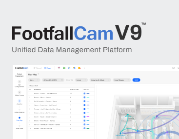
FootfallCam 3D Mini™ have a different coverage on Front View (91°) and Side View (45°). It required different calculation in order to ensure there is no obstacle blocking the view. Figure 1 illustrates the dual perspectives of the FootfallCam 3D Mini™, showcasing the Front View at 91° and the Side View at 45°.
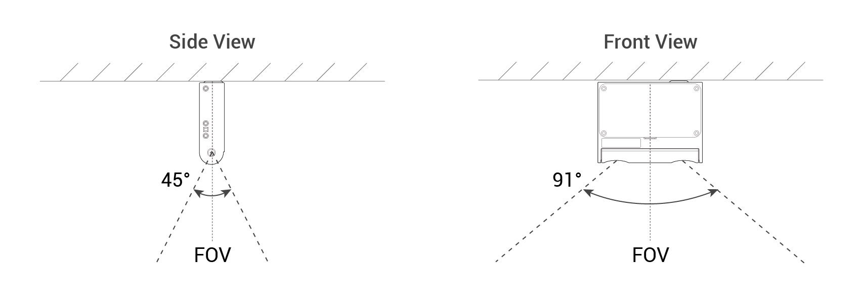 Figure 1: Side View and Front View of FootfallCam 3D Mini™
1.0 Understanding Clearance Distances: Visual Overview
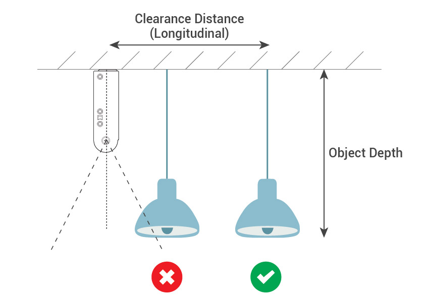
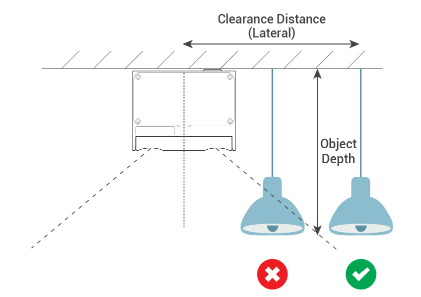
This section provides a visual presentation of added obstacles at recommended distances for both Longitudinal and Lateral perspectives, as shown in Figure 2. For detailed calculations, refer to Section 2.0 Formula.
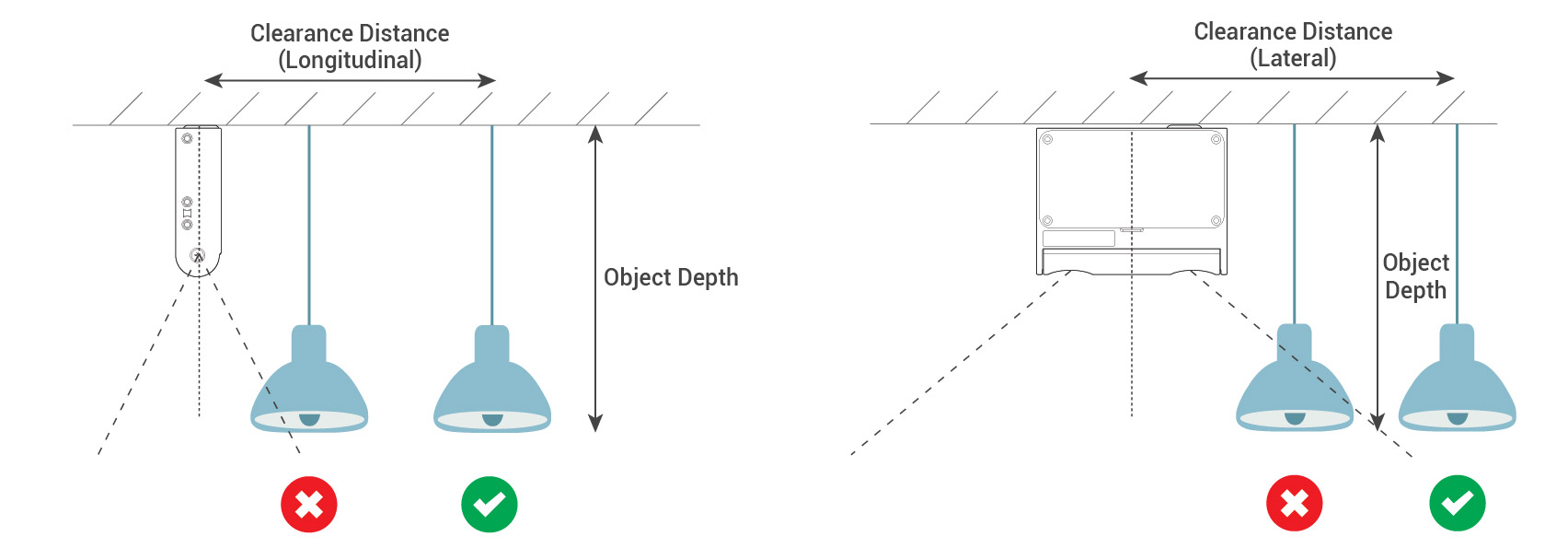 Figure 2: Obstacle Placement Overview
*Add tolerance to allow some error in location of installation*
2.0 Clearance Distance Formulas
This formula is applicable to both flat surface mounting with a drop-down obstacle and slanted surface mounting, providing a comprehensive solution for calculating clearance distance in various scenarios.
Figure 3 demonstrates the calculation for clearance distance, simplifying the understanding of this crucial measurement.
|
y = t + xtan α
|
Figure 3 |
2.1 Flat Surface Mounting for Drop-Down Obstacle
Calculate the min. clearance distance required between FootfallCam 3D Mini V3™ and the drop down obstacle (e.g. decorations, exit signage, bulk head, wall. etc.) to prevent the counter live view being blocked and not able to count accurately.
 |
 |
||||||||||||||||
|
Calculator (Longitudinal)
|
Calculator (Lateral)
|
2.2 Slanted surface mounting
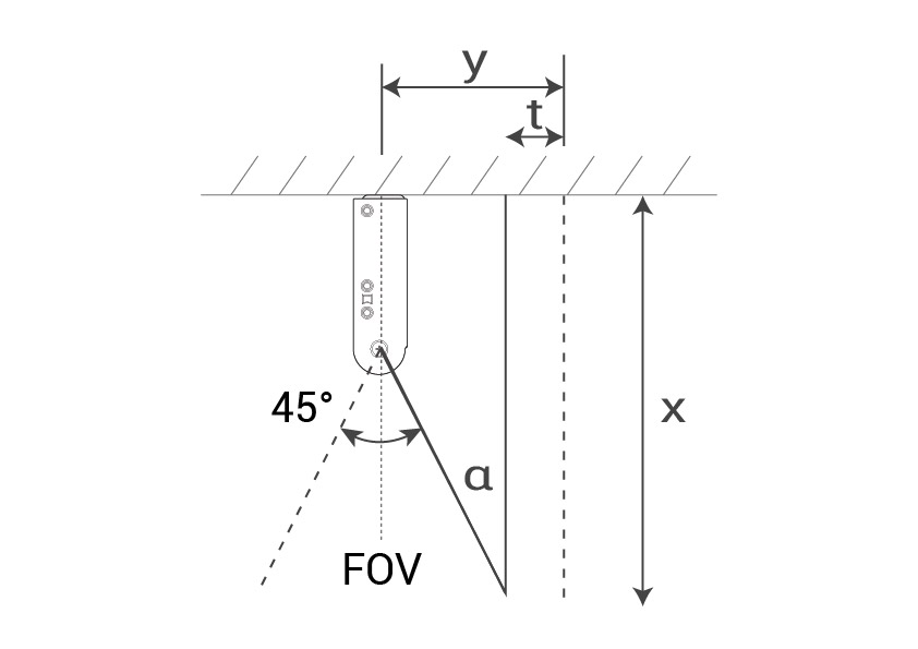
Calculate the precise angle required for slanted surface mounting using the same formula. Ensuring accurate placement for the FootfallCam 3D Mini™ and enhancing the counter's live view for precise counting.
Figure 4: Illustrates the FootfallCam 3D Mini™ positioned on a slanted surface, highlighting optimal angle placement for enhanced live view accuracy.
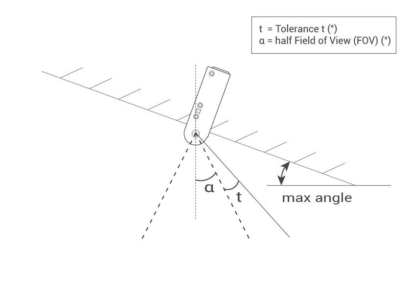 Figure 4: Optimal Slanted Surface Mounting
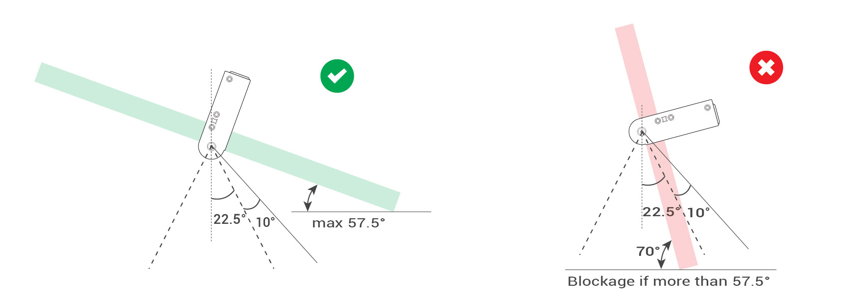 Figure 5: Optimal vs. Exceeded Angle Comparison
*Add tolerance to allow some error in angle measurement*
Conditions applied:
| tolerance t (°) | 10 |
| half Field of View (FOV) α (°) | 22.5 |
| max angle (°) | 57.5 |