


2.0 Installation Job Scope
-
Purpose Statement
- The purpose of this handbook is to be a reference to provide installers with the knowledge of the installers' job scope, price list, terms and condition, and general workflow. Installers must read through this handbook thoroughly to ensure complete understanding of the topics mentioned. Note that price listed servers as a reference and may be subjected to changes.
-
Work ethics
- As a certified installer for FootfallCam, installers must adhere to FootfallCam's installer work ethics.
-
By maintaining high standard of personal conduct.
-
By ensuring the installation is done with utmost professionalism.
-
By upholding responsibility for spoilages arising from mistakes.
-
By providing accurate measurements to ensure accurate installation will be done.
-
By fulfilling the scope of work provided throughout the installation.
-
By prioritising safety during the installation process.
-
By ensuring the orderly arrangement of the cables.
-
By ensuring work site is cleaned thoroughly after the completion of the installation.
-
By ensuring the FootfallCam counter(s) are in working condition after installation.
-
By striving towards high customer satisfaction through ethical conduct.
-
2.0.1 Installer's Job Requirement
FootfallCam's people counter is designed with the ease of installation in mind to ensure the workflow of FootfallCam installation goes smoothly without hassle. FootfallCam is committed to reducing the workload of our certified installers by providing clear and straightforward guide.
2.0.2 Skill Required for the installation
The installation for the FootfallCam counters is simple, there are only a few requirements that is needed for the installation process. The installer must have knowledge of:
-
The usage of smartphone for communication with the support team throughout the installation process.
-
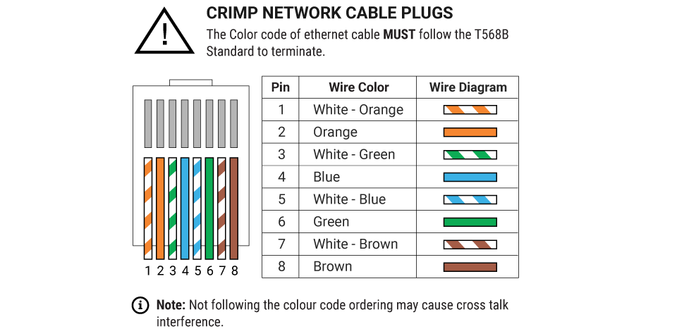
The crimping of Cat5 Network cables according to TIA/ EIA 568B colour code.
-
The usage of hand drill for the drilling of holes to mount the counters.
-
The basics of configuration network for the counter.
-
The usage of computer for onsite quick tuning.
-
The ability to conduct simple diagnostics based on the colour indicated by LED light on the counter.
2.0.3 Scope of work during installation
-
Installers will aim to have the cables to be hidden from sight, preferably above ceiling.
-
In any event that hiding the cables is unfeasible, the cables will be run within PVC/GI conduit/trunking.
-
The cables will have to be terminated and crimped according to TIA/ EIA 568B colour code.
-
The entrance has to be inspected in order to find an optimal spot for the counter (i.e.: away from swinging doors)
-
The counter needs to be mounted to the ceiling, wall bracket or drop pole may be needed depending on the height of the ceiling.
-
The 2 cables (1 from FootfallCam counter to the PoE, and 1 from PoE to the router) must be labelled.
-
The IP settings will be configured by the installers. (The installation site may have special IT requirements and the installer must configure the settings accordingly)
-
Simple tuning involving drawing the in and out line will have to be calibrated by the installer.
-
After the counter has been set up, it is the installers' duty to test the whether the counter function normally. If the counter does not function as intended, the request for verification button must be pressed.
-
The ceiling height measured by the installers will have to be correctly inputted into the software, along with the time zone. Ceiling height is measured as the height from the floor to the counter mounted area.
-
The Pairing Code provided by the customer will need to be entered into the IT details page in Device Manager.
-
Refer to the installation guide for comprehensive guide on the installation process.
2.1 Pre-installation Preparation
2.1.1 General Workflow
2.1.2 Installation Tools
 |
 |
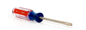 |
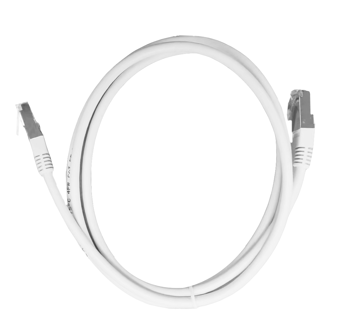
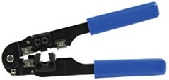
| Cat5 network cable to connect the counter from the midspan. | RJ45 crimp tool to terminate the cat5 network cable. | Screwdriver to fix the counter in place after mounting. |
 |
 |
 |
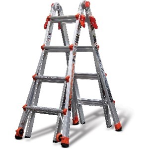
| Optional installation tool to conceal the cable after the installation. | General height of installation for counter ranges from 3 metres and above. | Scissor to reduce the length of the cat5 network cable. |
2.1.3 Site Survey
STEP 1 - Perform site survey of the environment prior to an installation.
STEP 2 - Complete the Site Survey Form to ensure the counter installation positioning.
|
Item |
Description |
|
Site Name |
Name of the branch. |
|
Site Code |
Code of the branch. |
|
Site Address |
Location of the branch. |
|
Person In-Charge |
Branch manager. |
|
Contact Number |
Contact number of the branch. |
|
Installation Date Time |
Preferred installation date time. |
|
Ceiling Height |
To determine the number of counter(s) require to fully cover the tracking area. |
|
Door Width |
|
|
Ceiling Composition |
To determine the ceiling suitable for physical installation or additional accessories needed. |
|
Floor Slope |
To determine the floor condition includes tilted or angled upwards. |
|
Head-end Distance |
To determine the distance from the back-office comms cabinet with router and midspan to the counter head. |
STEP 3 - Snap photo and check with FootfallCam to assist in determining the counter installation positioning.
 |
 |
 |
 |
 |
 |
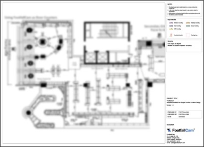
2.1.3.1 Floor Plan Preparation
STEP 1 - Provide ceiling height and measurement for coverage area to FootfallCam.
STEP 2 - FootfallCam will design the floor plan including quantity of counters required, cabling location and mounting position of the counter before every installation.
Sample Floor Plan:
2.1.3.2 Important Notes
- Take as many photos and videos as possible
- Photos and videos need to cover from multiple angles.
- Far shots - to be able to see overview (must be able to see ceiling, walk path and floor within the same photo).
- Close up shots - to be able to judge on mounting location.
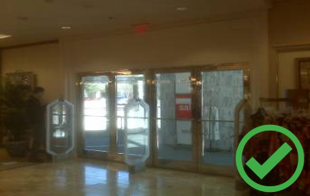
- Example of different angles:
- Sample 1:
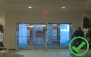
- Sample 2:
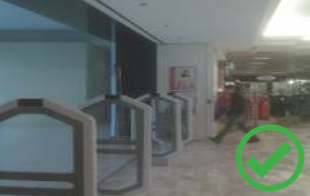
- Sample 3:
- Ceiling height dimension for all the location (mounting height and ceiling height)
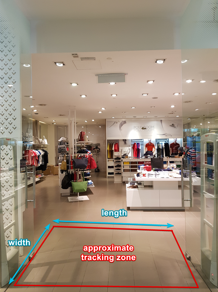
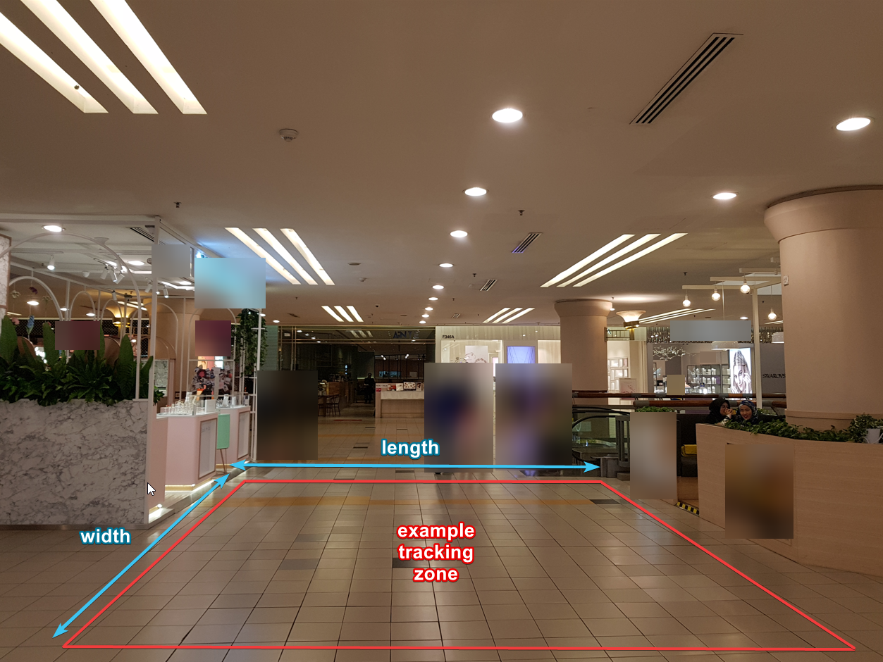
- Width and length of the tracking areas. Examples:
- To identify the location of the back office where the PoE switch or cabling will be connected.
- To plot the photos on the floor plan to indicate their respective locations.
2.2 Installing the Device
2.2.1 Cabling Guidelines
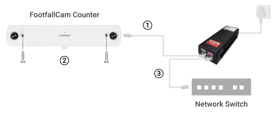
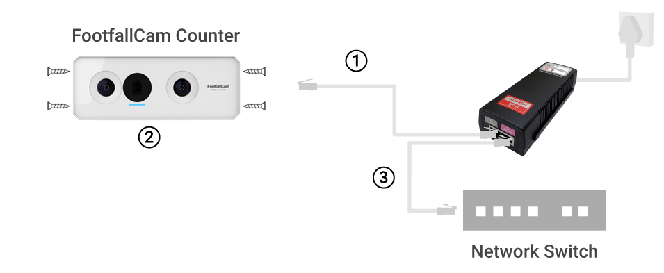
2.2.1.1 Connect using Single port POE injector
|
Option 1 - Connect with Midspan |
 |
|
STEP 1 - Connect Cat5e cable (self-prepare) from counter to midspan. STEP 2 - Plug in the counter and secure it onto the ceiling with screws provided. STEP 3 - Connect another Cat5e cable from midspan to router and turn the power on. |
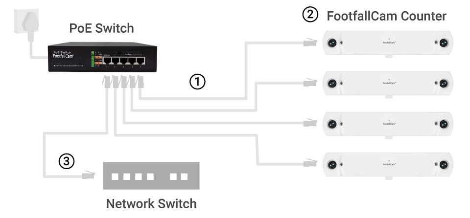
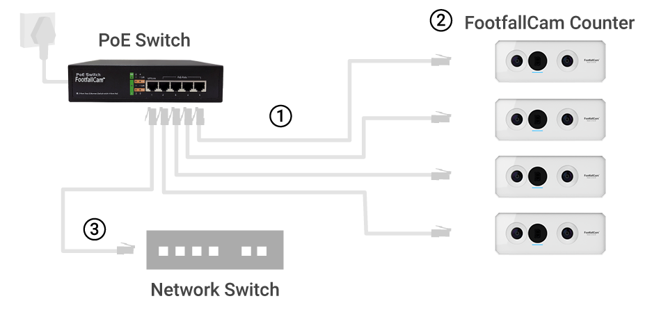
2.2.1.2 Connect using POE Switches
|
Option 2 - Connect with Powered over Ethernet Switches |
 |
|
STEP 1 - Connect Cat5e cable (self-prepare) from counter to PoE switches. STEP 2 - Plug in the counter and secure it onto the ceiling with screws provided. STEP 3 - Connect another Cat5e cable (Pink) from midspan to router and turn the power on. |
2.2.1.3 Cable Crimping standard
Installer MUST follow TIA / EIA 568B colour code for crimping the Cat5e cable to avoid crosstalk interference.
2.2.2 Device Positioning
2.2.2.1 Number of devices required
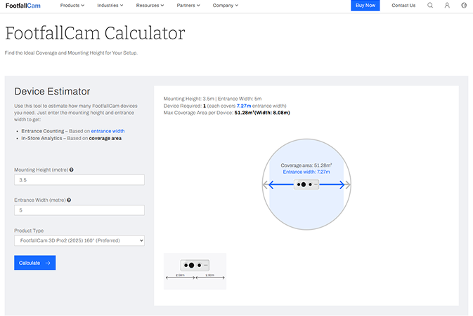
STEP 1 - Access to FootfallCam Calculator to determine the number of counter(s).
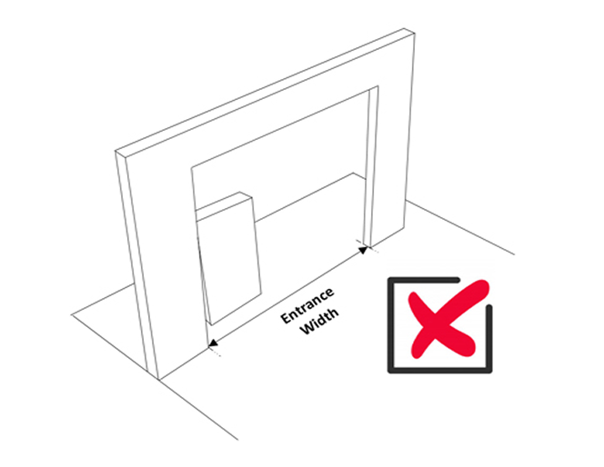
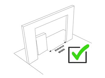
Some entrances are partially blocked by permanent unmovable obstructions, this should not be included when measuring the entrance width. Instead, the maximum potential pathway width should be measured.
*Note: If the counter that you have is not suitable for this ceiling height, please use a wall bracket or drop pole to ensure it is installed at the suitable ceiling height for this model. Please refer to FootfallCam Coverage Table.
 |
 |
STEP 2 - Complete the process by entering all the required fields and click on Calculate.
|
Item |
Description |
|
| Lens Type | 65° lens (Recommended ceiling height: 4.5m - 7.0m) | |
| 100° lens / 160° lens (Recommended ceiling height: 2.5m - 4.5m) | ||
| 140° lens (Recommended ceiling height: 2.2m - 2.5m) | ||
| Ceiling Height | 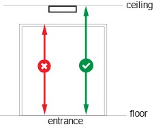 |
Measure from floor to the camera mounting height. |
| Door Width | 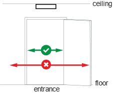 |
Measure the door width only on the walkable area. |
2.2.2.2 Ideal position for each entrance type
| Type of Entrance | |
|
|
 |
|
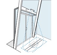
Sliding Door Counter require to install in the middle of the entrance perpendicularly down towards the floor. Counting line must align with the entrance and parallel to the door. |
Swinging Door Counter require to install at least 0.5 - 1 metre away from the door. Counting line must clearly define the swinging path and make sure the door is not overlapping the counting zone. |
 |
 |
|
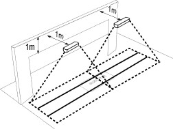
Wide Entrance Wide entrance requires multiple counters based on different ceiling height and entrance width. Use FootfallCam Calculator to identify mounting gaps between each camera. |
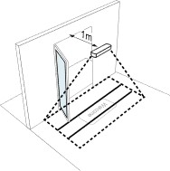
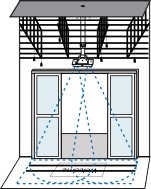
Open Ceiling Environment Use a drop pole to overcome the obstacles that are obstructing the live view of the counter. |
 |
 |
|
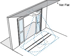
Slanted Ceiling Use a wall bracket on the along the side of the wall to ensure that the counter will be installed along an even surface. |
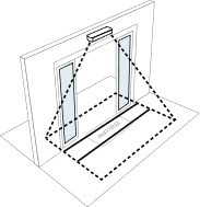
Glass Entrance Use a wall bracket on the along the side of the wall to ensure that the counter will be installed along an even surface. |
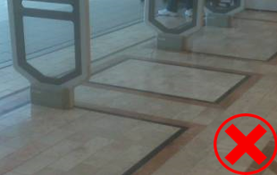
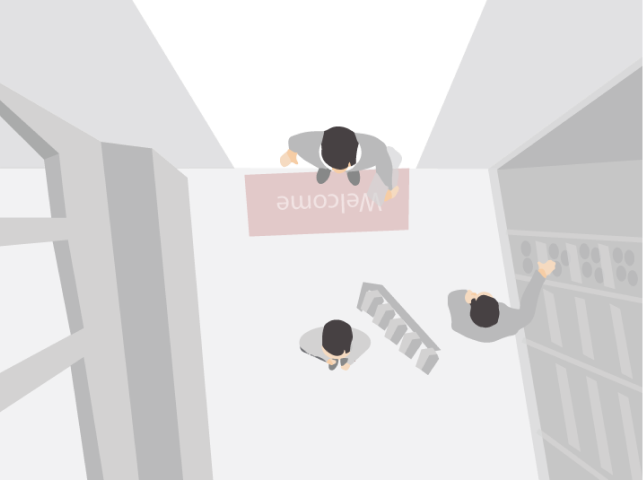
2.2.2.3 Scenarios of Device Position not Ideal
2.2.2.4 Obstacle to Avoid
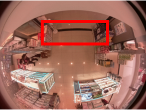
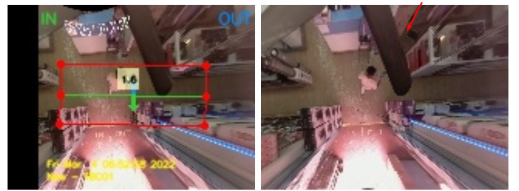
If the counter live view is blocked partially by the drop down obstacle, it may cause the counter not able to count accurately due to the limited tracking zone.
*Note: In most circumstances less than 20% of view being blocked shouldn't affect the counter accuracy.
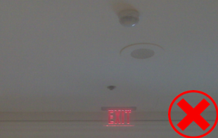
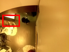
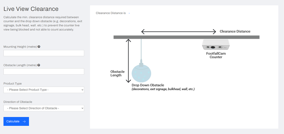
If there are any exit sign near the entrance, kindly try to measure the height of the sign board, then use the LiveView Clearance Calculator to check the clearance distance, using the lower section of FootfallCam Calculator.
For example:
The LiveView will be blocked by the exit sign in this position.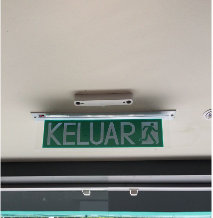
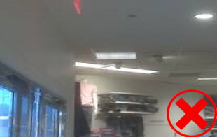
Other than that, kindly avoid any obstacle to be include in the device LiveView range, as it can cause the device not able to pick up counting accurately. Below is a bad example:
2.2.3 Mounting Options
How to install a 3D Pro2 to Ceiling, How to uninstall the Pro2 from Ceiling
https://www.youtube.com/watch?v=o7bupbGXTHU
2.2.3.1 Surface Mounting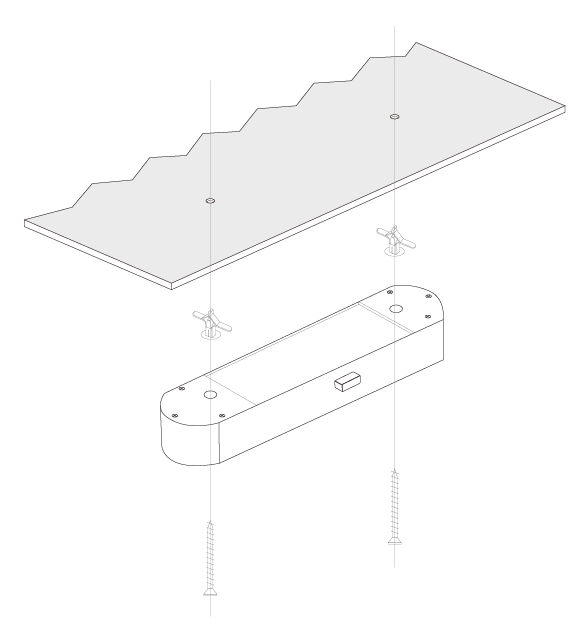
People counter is installed directly on the surface of the ceiling. This method is commonly used for installation and can be done easily.
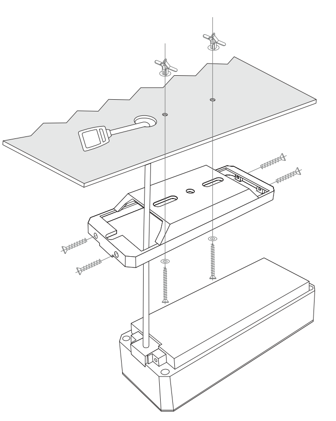
2.2.3.2 Flush Mounting
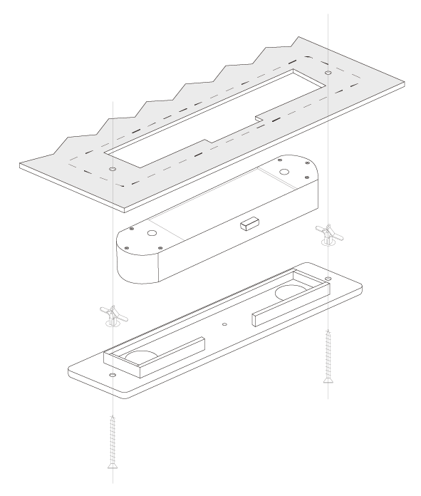 Customer may opt to use flush mount for installation should they wish to hide the people counter out of visibility.
2.2.3.3 Drop Pole Mounting
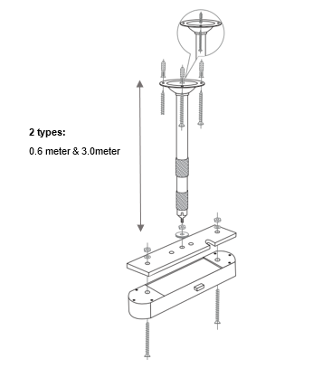 There are 2 types of drop pole which are 0.6 meters and 3.0 meters. Drop pole is used for installation when the height exceeds standard ceiling height of 4 meters.
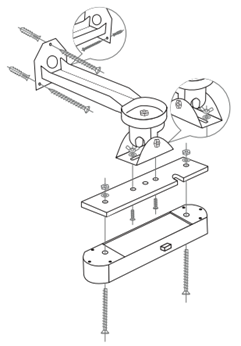 Customer may install people counter using wall bracket should surface mounting is infeasible based on store environment.