


The Staff Exclusion button is used to exclude staff footfall from the total footfall traffic. However it is different with the Staff Exclusion tag such that the staff is required to press the button upon entry or exit in an area where a counter is installed. This is the preferred solution for clients that have stricter rules for dress code at work.
-
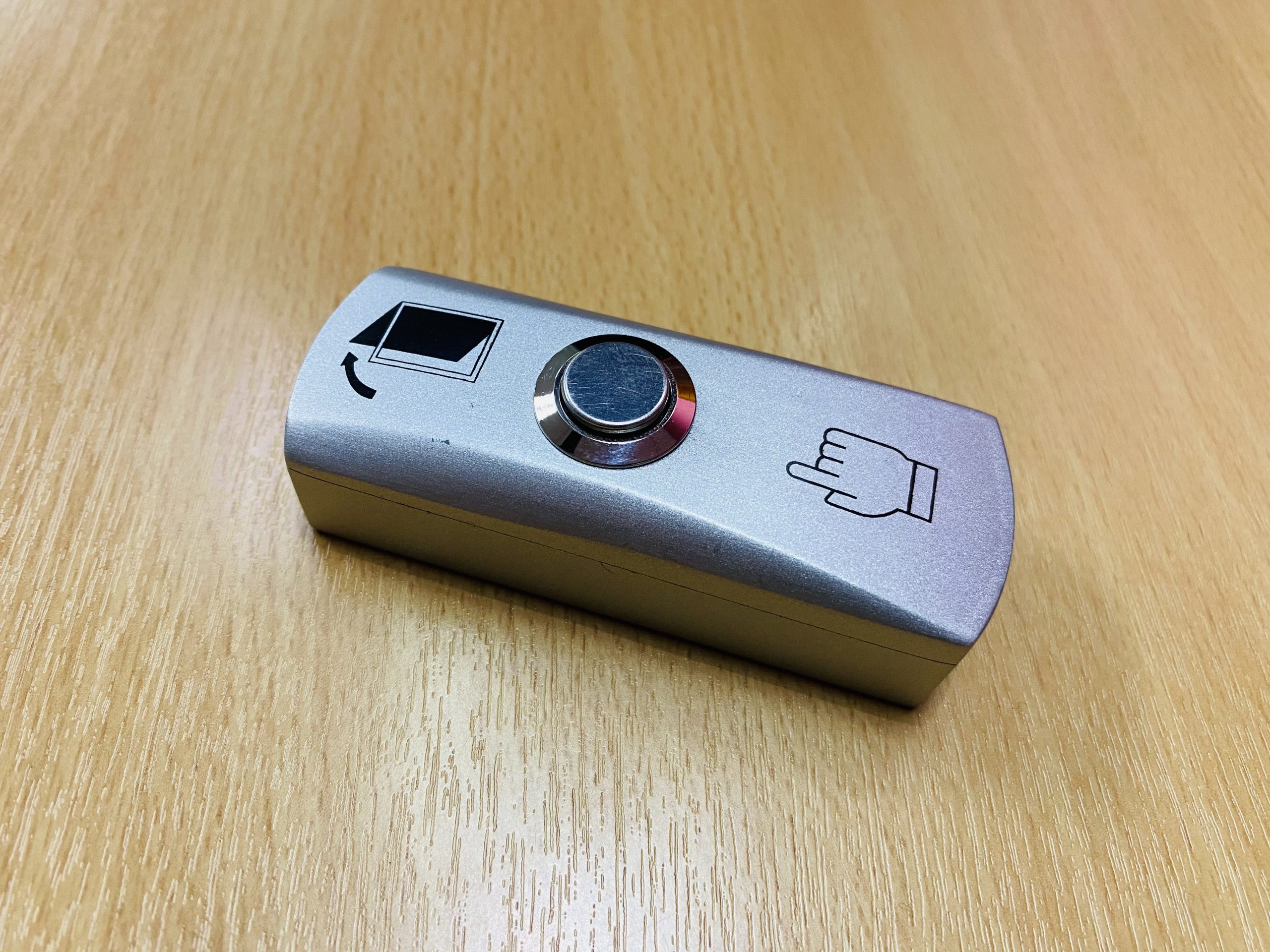
Staff Exclusion button (wired)
The Staff Exclusion button is usually mounted on the wall next to a doorway. There are 2 types of buttons, wired and wireless. The wired button can be connected the counter installed above the counting area. The diagram below shows the connection of the Staff Exclusion button to the counter.
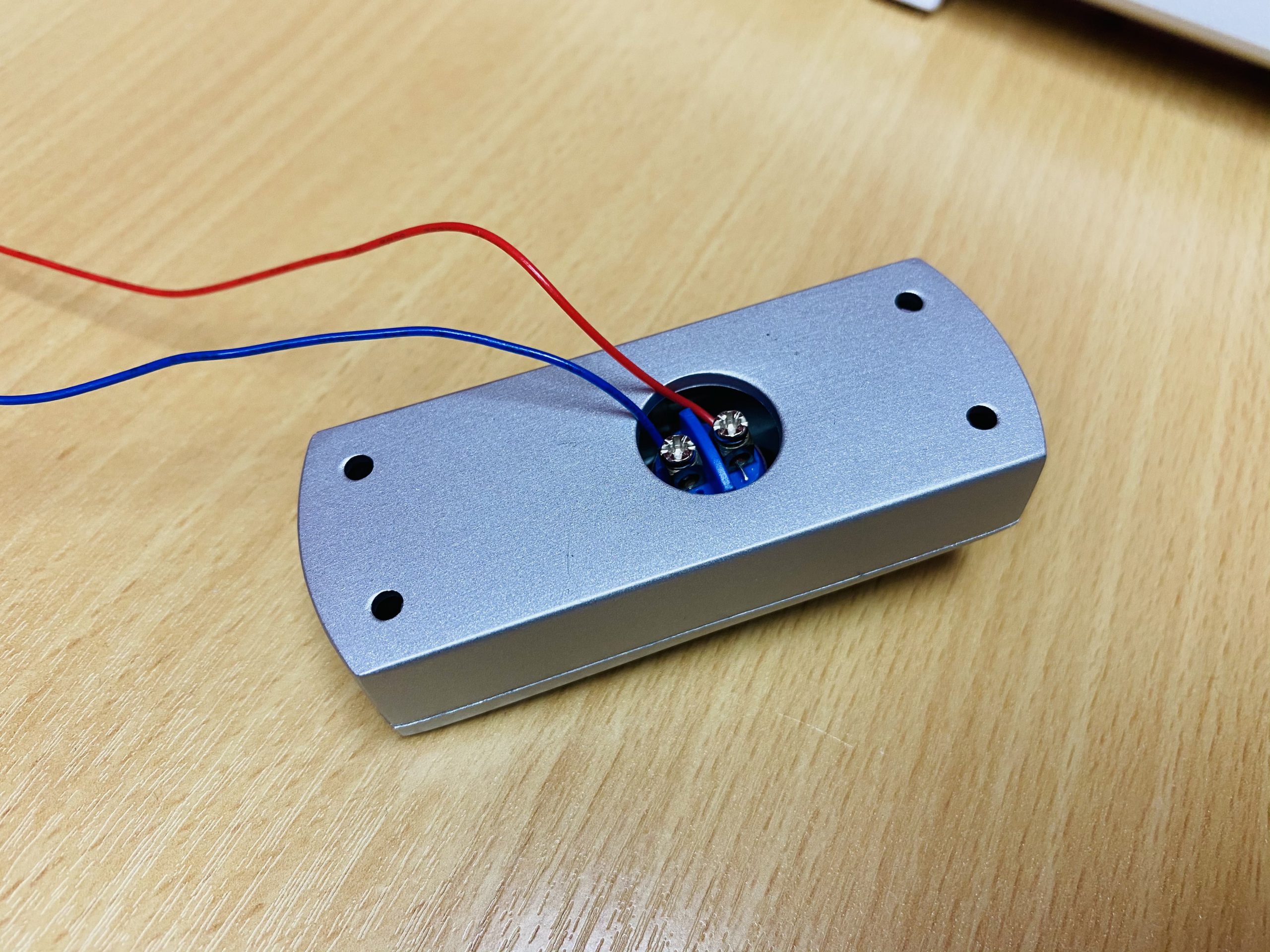
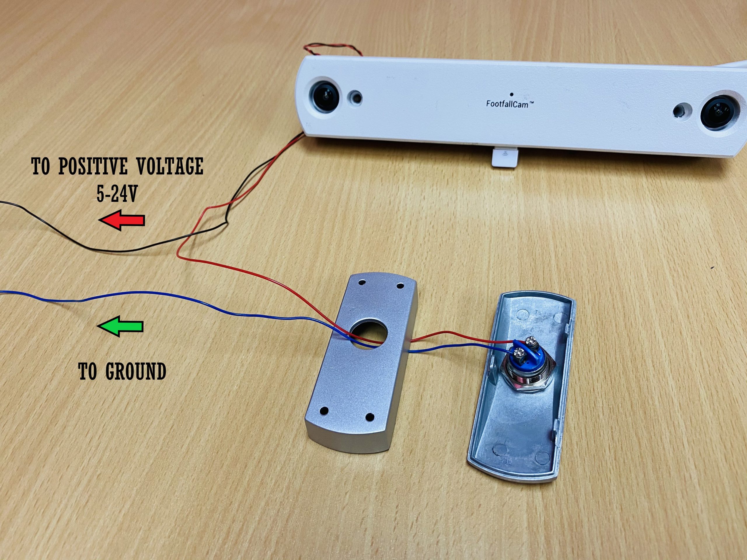
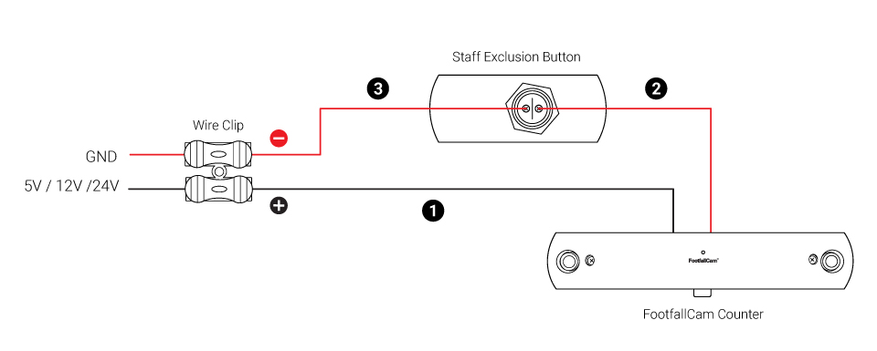 Wiring diagram of Staff Exclusion button (wired)
Connect the Black wire to a positive voltage (5-24V) and the Red wire to the button. Connect the other wire of the button to Ground. When the button is pressed, a signal will be sent to the counter to exclude the staff.
There is also a wireless version of the button. The wireless button has a range of about 5-10m depending on the environment. The wireless buttons works with Footfallcam™ SEV3 variant (Please contact our support for more information). Needless to say, these buttons offers more convenience and mobility since no wiring is required. There is however a caveat, the wireless buttons function as a universal remote to all the Footfallcam™ SEV3. The wireless button is not ideal in setups where counters are installed in multiple entrances/exits that are in close proximity. If a staff presses a button when someone is entering or exiting nearby, that person may also be excluded. In this case it is safer to use the wired button solution.
Staff Exclusion Button for 3D Pro2
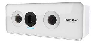
3D Pro2 Counter
3D Pro2 counter has a HDMI port which use for GPIO Usage or Staff Exclusion Button.
So Staff exclusion button for 3D Pro2 are are come with a button, a HDMI board and a wire clip.
Below images show the detail wiring connection and setup for staff exclusion button.
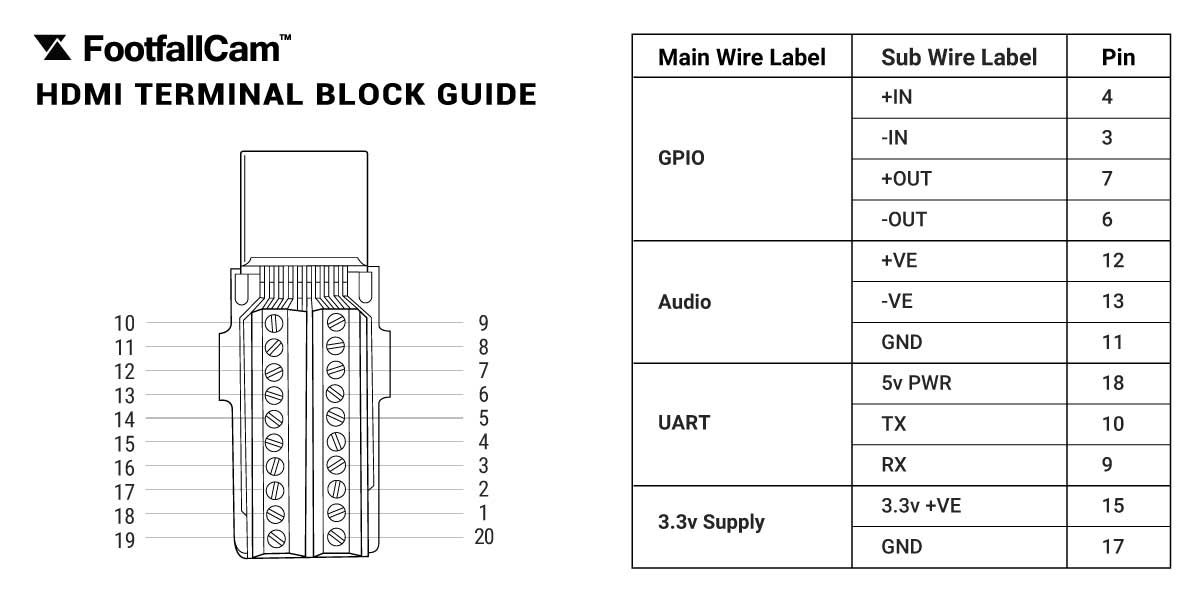
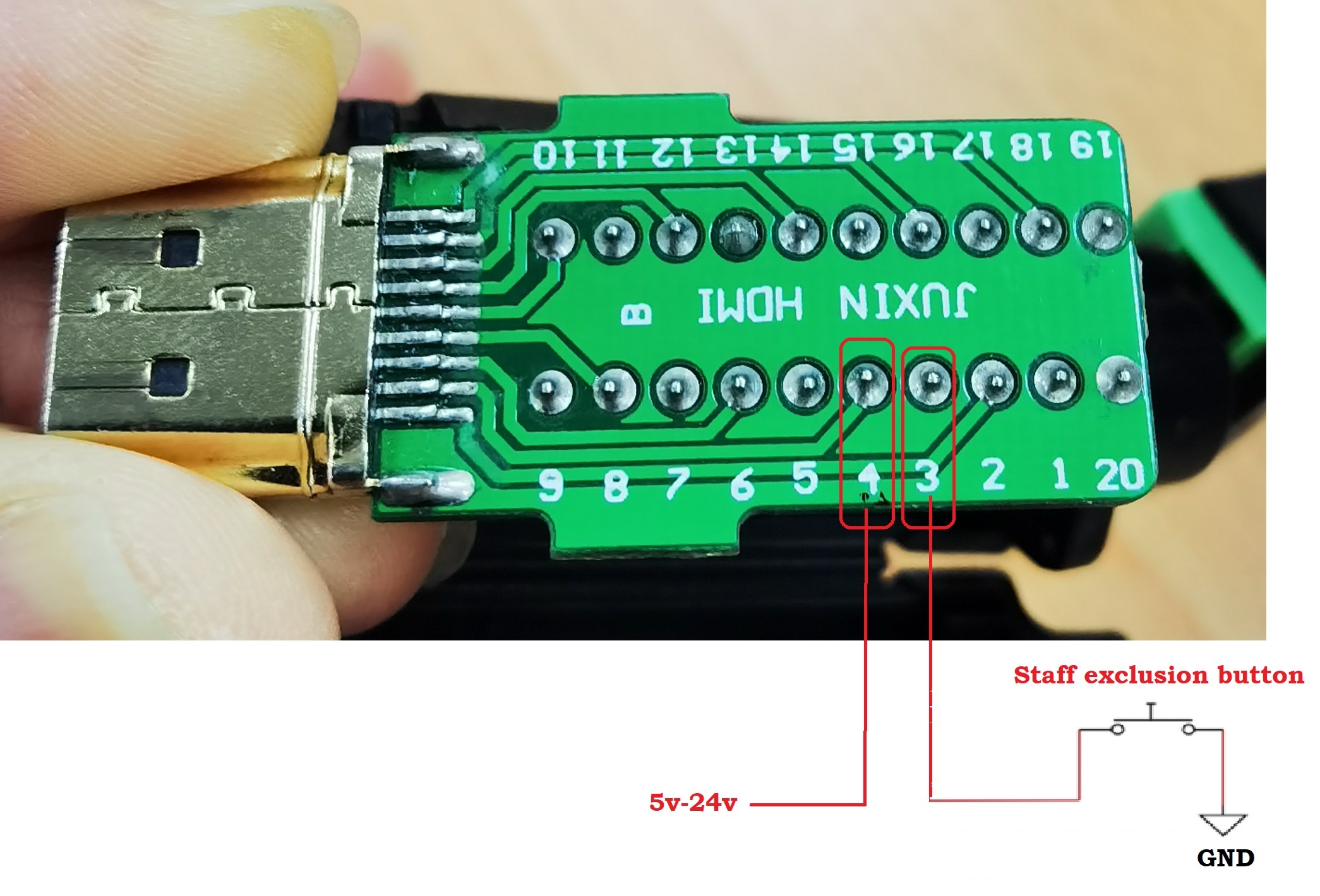 HDMI Board Connection
Connect 2 wire to Pin 3 and Pin 4 of the HDMI board
(Prefer Red wire for Pin 4 and Black wire for Pin 3)
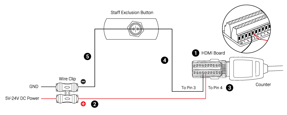
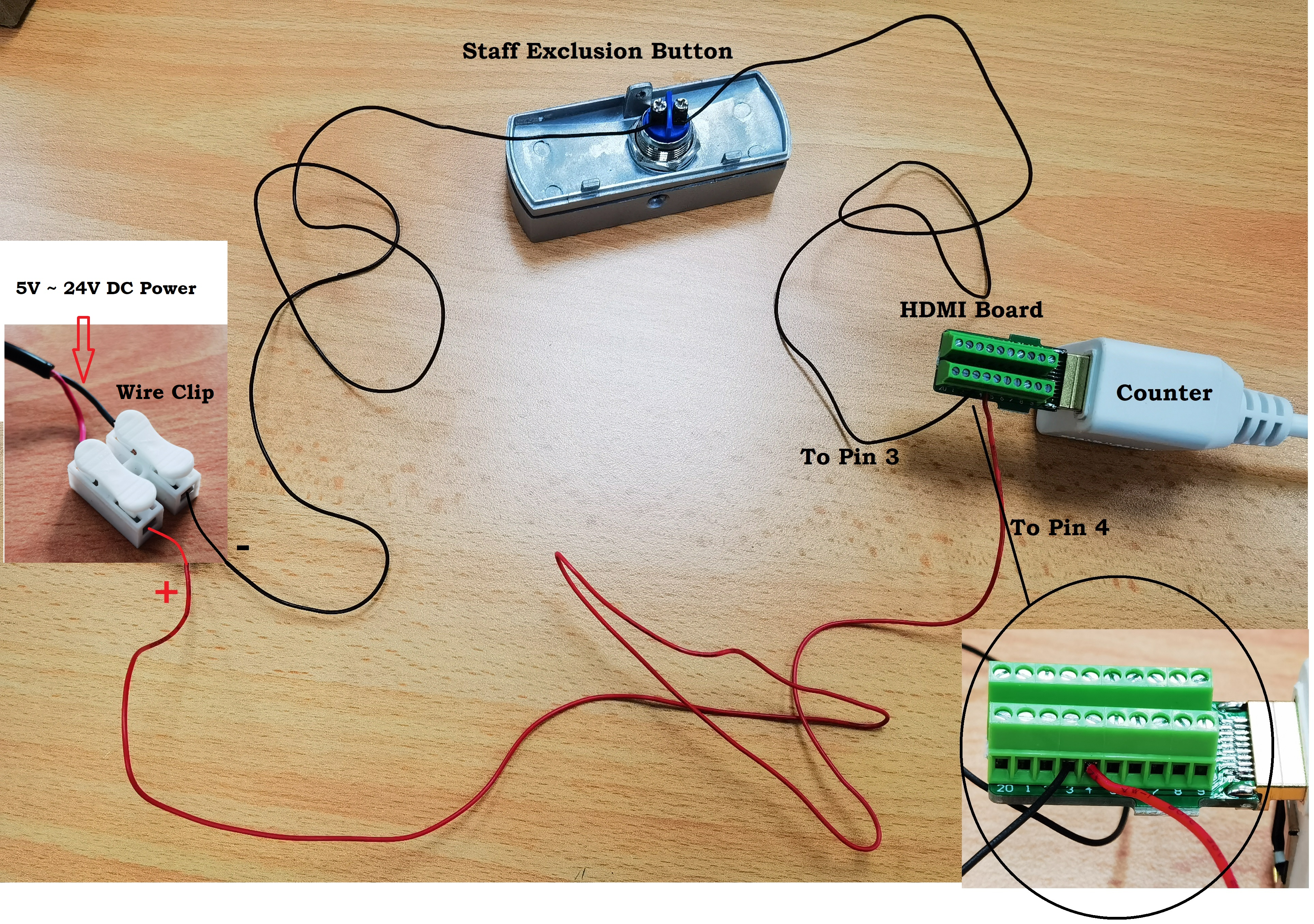 Wiring Diagram for 3D Pro2 Staff Exclusion Button
Connect the HDMI board, button, and wire clip together.
HDMI Pin 3 --> Button --> Wire Clip --> GND - (DC Power supply)
HDMI Pin 4 --> Wire Clip --> 5V~24V (DC Power supply)