


The counter provides a GPIO interface for controlling external devices such as an automatic door and traffic light. This feature is particularly useful in COVID-19 solutions where the venue requires more intervention to ensure stricter compliance to social distancing regulations.
The counter exposes 2 GPIO output wires for control. The output wire color schemes are either green(+)/yellow(-) or grey(+)/brown(-). These wires are opto-isolated GPIO output and does not source power.
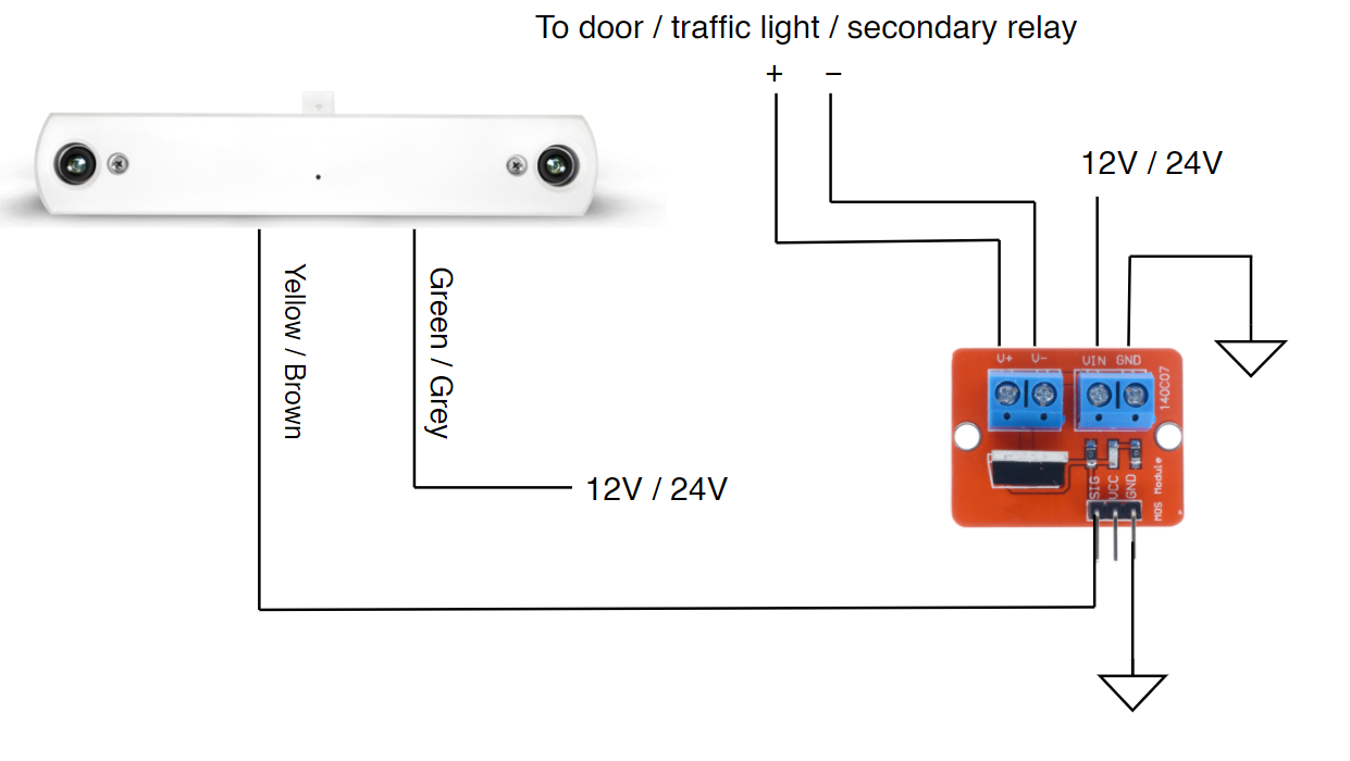
The optocoupler can only switch up to 30mA of current. More often than not the controlled device need much higher current than this, therefore a driver or relay is needed to switch the higher current.
The diagram below shows the connection from FootfallCam™ counter to a driver module which is in turn connected to a automatic door or traffic light. The module used in this example has a maximum continuous current limit of 9.2A which is sufficient for most automatic doors and traffic light. A secondary relay can be used if even higher currents need to be switched.
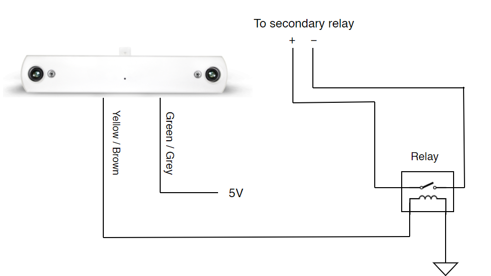
Another option is to use a 5V mechanical relay. The relay coil should have a power rating of 40mW or less due to the drive limit of the GPIO pin (8mA). This relay can be connected to a secondary relay of higher rated current to control the door or traffic light.
The counter can also be connected to a buzzer to sound an audio alert when the venue's maximum capacity is breached. The choice of implementation is not limited to these and is up to the user's creativity.
More Technical Information
At the fundamental level, the GPIO circuit uses an optocoupler to isolate the counter from external electrical signals for protection. The optocoupler used is ILD207T from Vishay Semiconductor. The circuit in the counter is designed to drive voltages in the range of 5-24V.
Optocouplers are designed for isolation and not for driving high currents, therefore an external MOSFET or relay is require to drive devices that require more than a few milliamps. The drive circuit is not designed into the counter to allow for more flexible integration.

Source: Wikipedia
Verifying Connections
To test the pin connection or relay output, connect to device SSID via Wifi and navigate to 192.168.4.1/GPIO.html. This simple UI serves the purpose of checking pin status as well as testing to change the pin status.
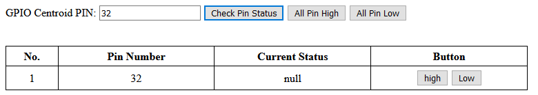
| Check Pin Status |
Key in the GPIO pin number to check for its current status:
|
| All Pin High | Set all pin status to high output voltage |
| All Pin Low | Set all pin status to low output voltage |
| Button 'high' or 'low' | Set that particular pin status to high or low output voltage accordingly |
Changing pin status is instantaneous. The default GPIO pin number is:
| Counter | Pin 32 |
| Centroid | Pin 31, Pin 33 |