


1.0 Pre-Installation Preparations
Preparation Checklist
-
Sufficient Copper wires, Cat5 cable, Ethernet straight cable
-
Screw Drivers and Drill
-
Windows-based Laptop to configure devices
-
Android mobile device with Bluetooth to set up devices
Pre-installation To-dos
-
Identify the APN of the SIM Card (to input into Mesh Hub during device configuration). You can view your APN settings in one of the following locations:
-
For Android, go to: "Settings" > "Connections" > "Mobile networks" > "Access Point Names".
-
For IOS, go to "Settings" > "Mobile" > "Mobile Data Network".
-
For Pixel, go to: "Settings" > "Network & Internet" > "Mobile network" > "Advanced" > "Access Point Names"
-
-
Identify from end client on available 12V power source on-board (usually from vehicle battery) which can be used to power the system
-
Identify from end client on the Control Signal for bus door (signal output provided by the bus system which is responsible for controlling the opening and closing of the door). This signal will be connected to GPIO pin of 3D Mini V3
-
Download and install FootfallCam Installation App at your mobile device via this link (currently support Android version only).
-
Download Mesh Hub Configuration Executable File to your laptop via this link
2.0 Installing the Device
2.1 Setting Up 4G Mesh Hub
1. Unscrew and remove the front cover of the Mesh Hub.
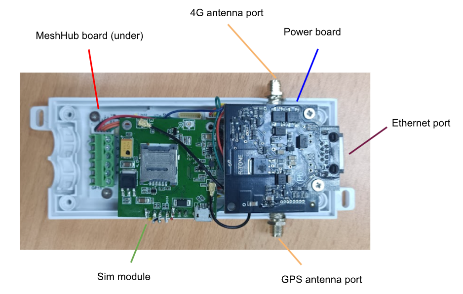
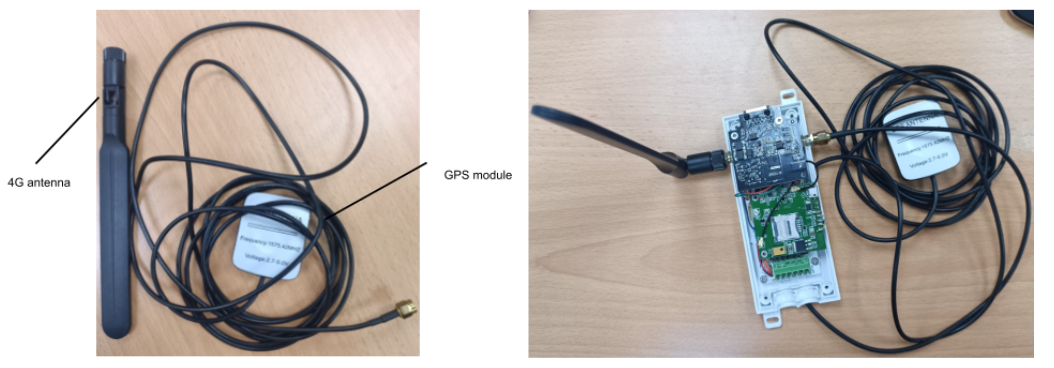
2. Connect the antenna and GPS module to the Mesh Hub by screwing the ends to their respective ports:
3. Insert the Sim Card (prepared by End User) into the Sim module.
2.2 Wiring Diagram
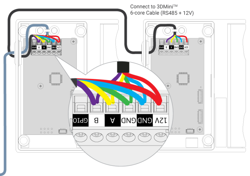
Connection Diagram (for Mesh Hub and 3D Mini)
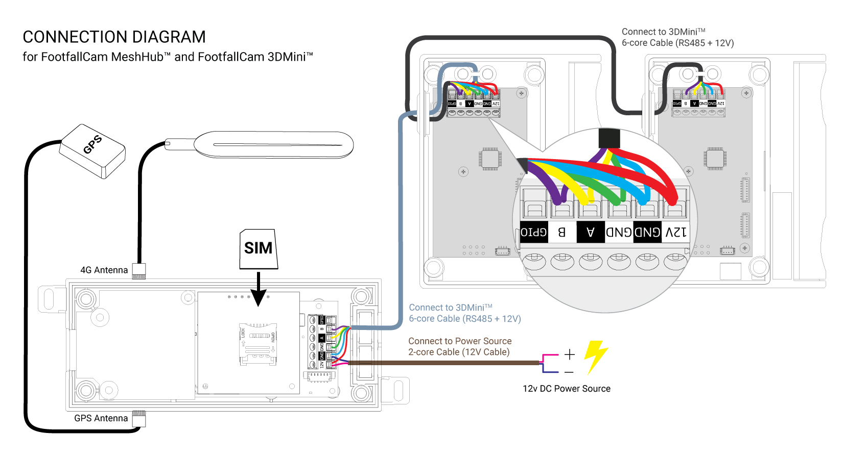
1. Connect the 12V and GND pin of Mesh Hub to a 12V DC power input, secure the wiring to the terminal block with a screw driver, DO NOT power up yet.
2. Connect the 5 pins on Mesh Hub (all pins except GPIO pin) to the respective 5 pins on 3D Mini using RS485 cable. Secure all wiring to the terminal block. Make sure each pin on the Mesh Hub is wired to the corresponding pin on 3D Mini using the same wire (as shown in the diagram above, indicated with different colors).
2.1. If you need to chain up a 2nd 3D Mini to Mesh hub, simply use another RS485 cable to connect the same 5 pins on the 1st 3D Mini to the respective 5 pins on the 2nd 3D Mini. Repeat the same connection for each subsequent 3D Mini added (i.e. chain up 2nd 3D Mini to 3rd 3D Mini, and the 3rd one to the 4th one, and so on.).
3. Turn on the 12V power source. The Mesh Hub will boot up, with its LED blinking GREEN during the initialization process. The LED should settle down in BLUE lighting once the initialization is completed. (Note: if the device is indoor, it might have difficulty to obtain GPS signal, hence LED will be in PURPLE lighting).
Connection Diagram (for direct integration of 3D Mini)
1. Open up the cover of 3D Mini, expose the 6 labeled ports on the terminal block within the 3D mini.
2. Connect the 12V and GND pin of 3D Mini to a 12V DC power input, secure the wiring to the terminal block with a screw driver, DO NOT power up yet.
3. Connect pins on position 3 to 5 (GND, A, B) from the 3D Mini to the base station using RS485 cable and RS485 Serial Bus Converter Module (Note :In case of using a laptop as base station, a RS485 to USB converter may be needed instead). Secure all wiring to the terminal block. Make sure each pin on the 3D Mini is wired to the corresponding pin on the base station.
4. If you need to chain up a 2nd 3D Mini to the base station, simply use another RS485 cable to connect the same 5 pins on the 1st 3D Mini to the respective 5 pins on the 2nd 3D Mini. Repeat the same connection for each subsequent 3D Mini added (i.e. chain up 2nd 3D Mini to 3rd 3D Mini, and the 3rd one to the 4th one, and so on.).
5. Turn on the 12V power source, the 3D Mini should boot up and working.
6. Sample script on how to poll data from 3D Mini can be found here.
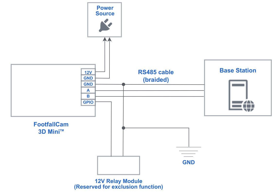
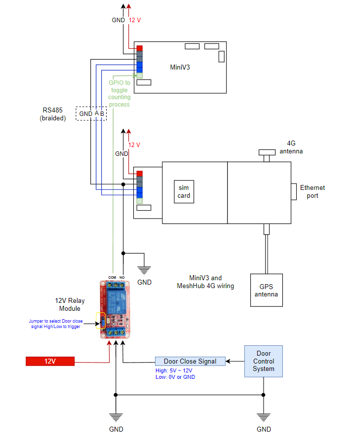
GPIO Connection
-
GPIO connection is required to make sure that the counting process is halted as long as the door remained closed, so that 3D Mini does not capture noise counts when the bus is moving. Remember to turn off the power source when wiring up the connection.
-
A relay module is provided by FootfallCam along with the device. On top of the existing connection shown in section 2.2, connect the COM pin and the NO pin of the 12V relay module to the GPIO pin and GND pin of 3D Mini respectively (refer diagram above for illustration).
-
Supply 12V power source to the DC+ pin of the relay module. Connect the door close signal output (could be High or Low, need to adjust the jumper accordingly) from the door control system to the IN pin of relay module. Make sure the DC- pin of relay module is connected to the common ground as the door control system.
2.3 Device Positioning
You can choose the most appropriate mounting location as long as it fulfills the following criteria:
-
Mounting height should not exceed 2.2m. Consult FootfallCam personnel if it is impossible to meet the height limitations, a bracket can be used the extend the device out from the side wall.
-
The vertical distance between the top edge of the door to the device location CANNOT be More than 10cm.
-
Ensure that the counter view is not blocked by any drop down obstacle. Refer to Clearance Guidelines.
-
Ensure that both lenses are facing downwards perpendicularly.
-
The counter should be installed in the middle of the entrance
-
Ensure that the bus entrance is within the coverage area of FootfallCam 3D MiniTM. Refer to the coverage table.
Here are some examples of how the device can be installed for different bus entrances:
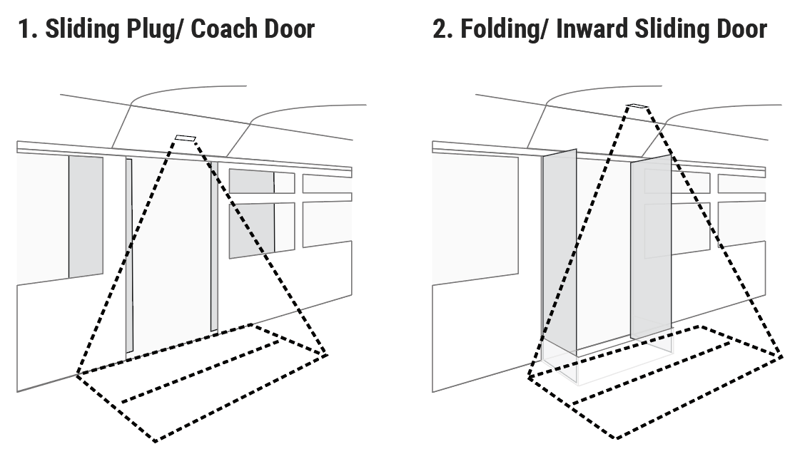
Note: For bus entrances with doors that can be swung inwards (e.g.. Diagram 2), GPIO connection is highly recommended to pause counting when door is opening or closing. But if GPIO is not available, the device would need to be installed inwards to avoid the doors.
3.0 Device Configuration
3.1 Configuring Mesh Hub 4G Network Settings Via Bluetooth
This section describes the steps of configuring Mesh Hub 4G network settings via Bluetooth connection.
-
First of all, kindly make sure that the device is powered up.
-
Download the executable file from this link.
-
Open up a command prompt, change directory into the folder with the executable file, enter the command "MeshHubConfiguration.exe <MAC_ADDRESS_OF_DEVICE> sim" and press ENTER. See image below for an example:
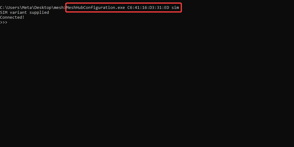
4. You should see the connected! in the command prompt if connection to Mesh Hub is successfully established.
5. The following table shows a list of supported commands along with their expected response and description. Make sure the two compulsory parameters for Mesh hub 4G, namely the SIM endpoint and APN which correspond to row 9 and 11 respectively are SET correctly, by entering the relevant command into the command prompt. Always use the GET command to confirm whether a parameter is successfully updated. With the correct parameters being set, the LED of Mesh Hub 4G should be showing static BLUE light, indicating the device is online and ready to send data upstream.
|
No |
Command Number |
Response |
Description |
|
1. |
>>>0 0 |
<MeshHub Type> , <Version>,<Device UID> , <Company Serial> |
To get the Basic Info of Mesh Hub. |
|
2. |
>>>3 0 |
<Serial> , <Serial> , <Serial> ... |
To get the number of Mini V3 Connected and the serials of them |
|
3. |
>>>3 1 MiniV3 Serial |
<Device Type> , <Device UID> , (Active/Inactive) |
To get the Basic Info of the Mini V3 |
|
4. |
>>>4 0 |
RESCANIT! |
To Rescan the Mini V3 Connected to Mesh Hub (Do this When Connect a New MINIV3) |
|
5. |
>>>9 0 |
0 or Others (0 = OK) |
To get POST Status |
|
6. |
>>>10 0 |
|
To get the Sim Current Startup State, The status should be READY when the sim is ready |
|
7. |
>>>11 0 |
<IMEI> |
To get SIM IMEI (International Mobile Equipment Identity) |
|
8. |
>>>12 0 |
<URL> |
To get the SIM ENDPOINT points to. |
|
9. |
>>>12 1 URL |
OK/Others (Ok means no Issue) |
To set the SIM ENDPOINT, by default URL should be : http://ws.footfallcam.com:54541/MeshHub/PostMeshhubPayload , If customer is not using own server. |
|
10. |
>>>13 0 |
<APN> |
To get Access Point Name(APN) from the SIM |
|
11. |
>>>13 1 APN |
OK/Others(Ok means no Issue) |
To set Access Point Name(APN) of the SIM |
|
12. |
>>>14 0 |
<PIN> |
To get the PIN of the SIM |
|
13. |
>>>14 1 PIN |
OK/Others(Ok means no Issue) |
To set the PIN of the SIM (Only four digit allowed) |
|
14. |
>>>15 0 |
<URL> |
To get NTP SERVER URL from the SIM |
|
15. |
>>>15 1 URL |
OK/Others(Ok means no Issue) |
To set SIM NTP SERVER URL, default should be 0.pool.ntp.org |
|
16. |
>>>16 0 |
<Value>ms |
To get GPS QUERY PERIOD, it is the period the query gps coordinate every <value>ms |
|
17. |
>>>16 1 Value |
OK/Others(Ok means no Issue) |
To set GPS QUERY PERIOD, default value is 5000. Unit is milliseconds. |
|
18. |
>>>17 0 |
<Time of last query> (<second since last query>) |
To get GPS STATUS, the time of the last query and the time since last query in seconds. |
3.2 Getting Counting Data from 3D Mini without Mesh Hub
1. Connect the 3D Mini to the base station using RS485 cable.
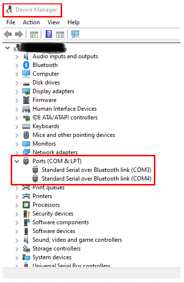
2. Find the port number on the base station which is connected to 3D Mini. For windows, the active port number can be found under Device Manager > Ports (COM & LPT)
3. Ensure that the base station is equipped with Python and that the environment is configured according to the requirements.txt file provided along with the python script.
4. To execute the Python script, navigate to the directory containing the script and run the following command. Remember to modify the argument as necessary for your specific environment.

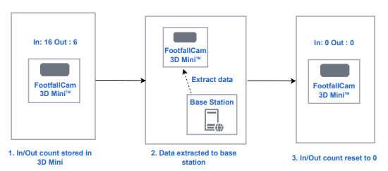
5. Upon successful execution of the script, the base station will retrieve the cumulative in/out count from the 3D Mini and subsequently reset the stored count on the device. The maximum number of accumulated counts for in/out count will be 65535 each (Equivalent to 2 bytes).
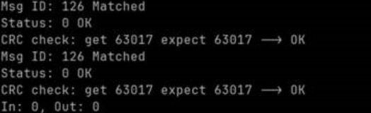
6. The example successful output should be something like this:
3.3 Accessing the Devices
1. Launch FootfallCam Installation App at your mobile device.
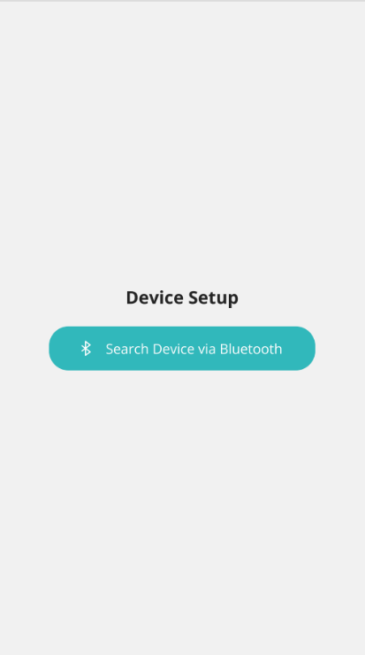
2. Turn on your phone's Bluetooth and search for FootfallCam devices (Note: All Bluetooth-enabled devices will appear in the page).
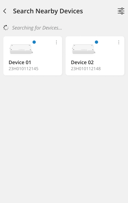
3. Devices detected will appear in the app page. Tap on the correct serial to proceed with the set up.
3.4 Configuring Mesh Hub through Mobile App
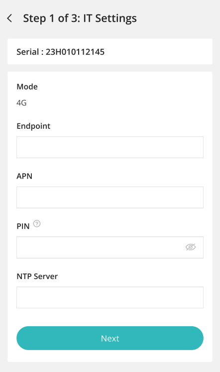
Endpoint - By default the endpoint would be http://51.89.155.156:54541/MeshHub/PostMeshhubPayload which is FootfallCam Cloud Server. If client is NOT using FootfallCam's Server, insert the server endpoint which the data will be sent to.
APN - Refer the Pre-installation To-dos to find out the APN of your SIM card
PIN - Sim Card Pin Number (if PIN is set)
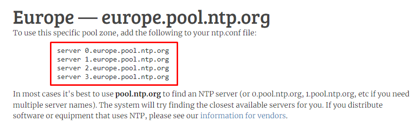
NTP Server - Go to https://www.ntppool.org/ and select the region that the installation site belongs to. Insert the ntp.conf file (e.g. server 2.europe.pool.ntp.org)
3.5 Configuring 3D Mini through Mobile App
3.5.1 Setting Up Device
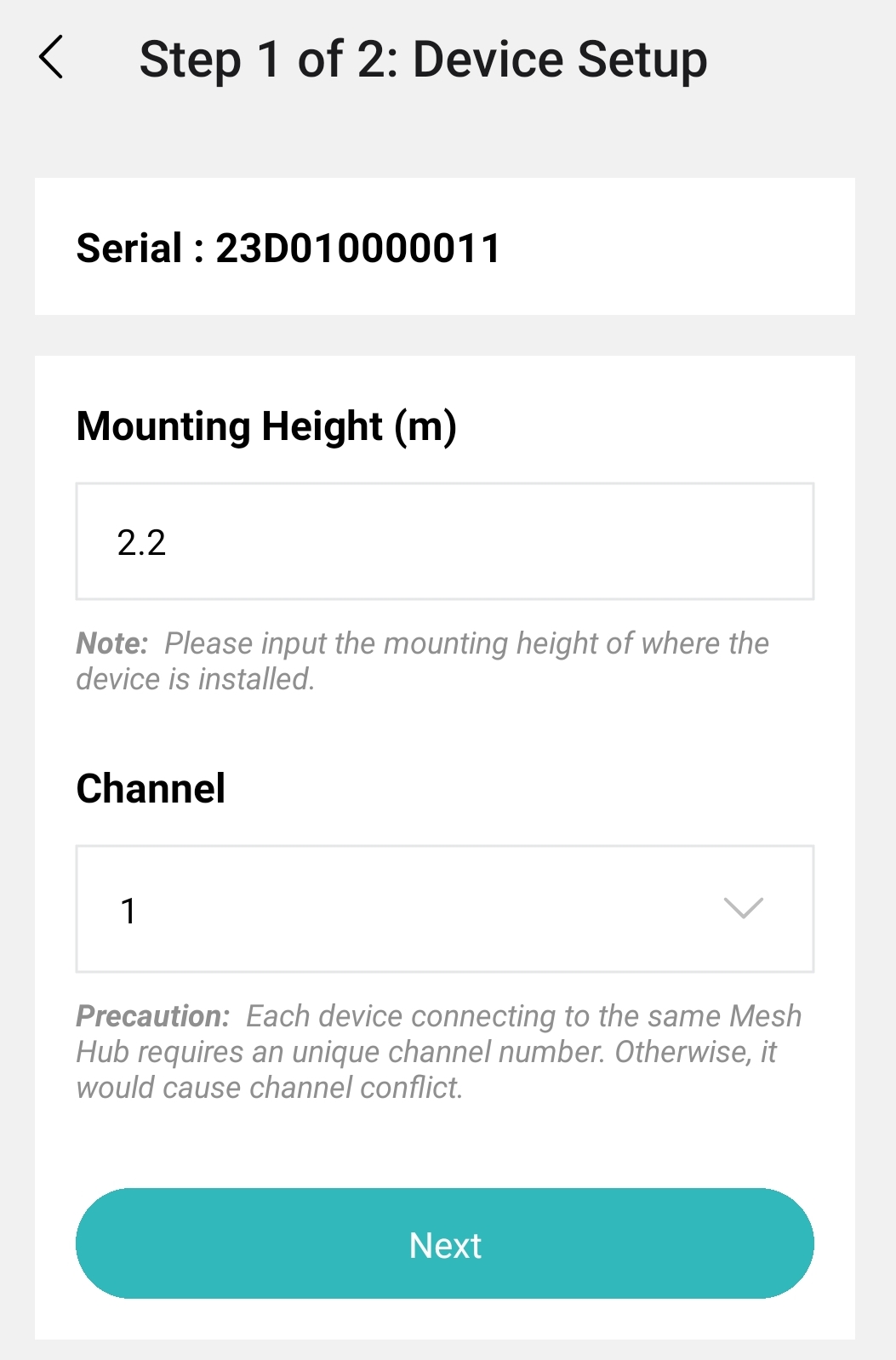
Mounting height (m) - The perpendicular distance from the floor to the location where the device is mounted.
Channel - For identification of device. DO NOT use the same channel number if there are more than one device connected to the same Mesh Hub.
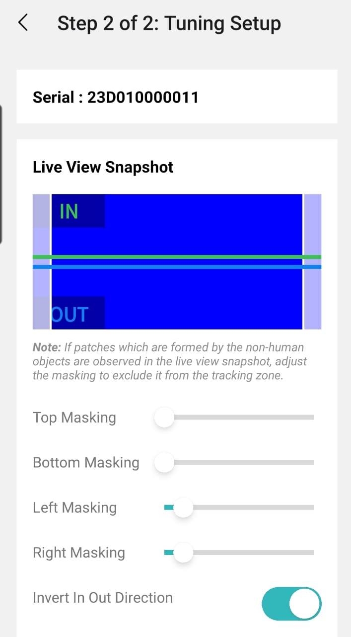
Live View Masking - To eliminate any potential noises. Adjust the masking by toggling the Top, Bottom, Left and RIght masking. Mask nearby objects (seen in colour patches) and ensure that the unmasked area covers only the entrance area
Human Height Range (m) - Any object detected with a height that is outside of the range will not be included in the counting.
Pause Counting Duration (s) - The duration here is the buffer time for bus doors to close completely before system pauses counting. The same duration applies for the opening of bus doors, it is the buffer time before system resume counting.
-
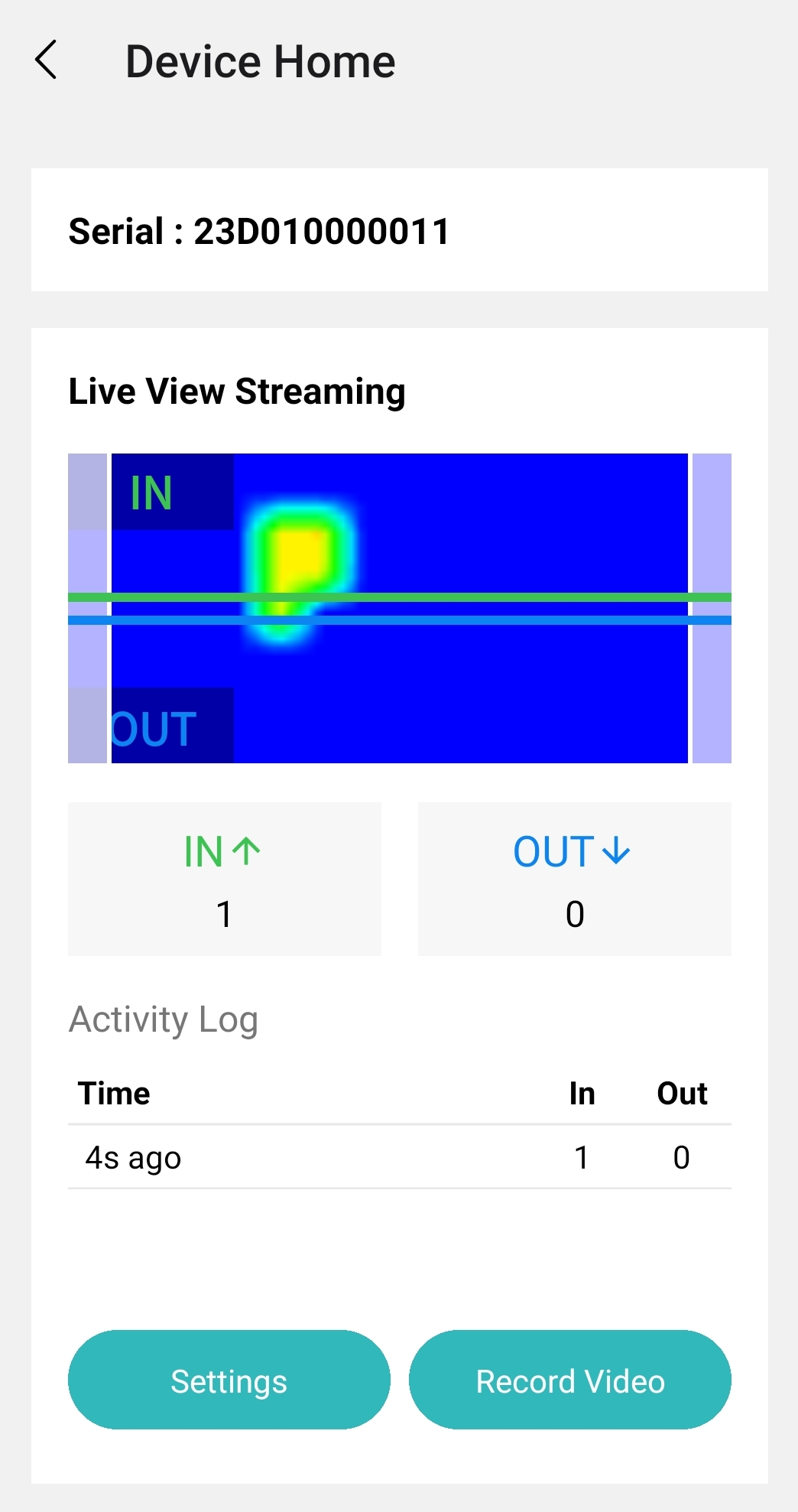
After Tuning Settings is applied, walk below the device to see if heat signal is displayed at the Live View Streaming.
-
If the IN/OUT direction does not reflect the actual site environment, go to "Settings" and Invert the In Out Direction using the toggle.
-
If device is not counting as expected, try to readjust the settings (masking, human height range and pause counting duration) depending on the issue. If issue cannot be resolved, proceed to record a walk test for FootfallCam Support personnel to look into it. Use your mobile device built-in screen recording function to record a video and share the file with us.
3.5.2 Record Walk Test video with PC
1. Get the executable file from here to record walk test video from PC via Bluetooth connection.
2. Open up a command prompt and navigate to the directory containing the downloaded executable file. Enter the command "sensor_stream_pc.exe <3D_MINI_MAC_ADDR> --record" to start the recording.
3. Move IN and OUT of the entrance that the device is covering. Perform at least 30 IN and 30 OUT using different possible ways a visitor would enter/exit the area.
4. Once you have collected sufficient sample size, press on "q" to stop the recording. The recorded file can be found in the same directory as the executable file.