









FootfallCam Centroid Configuration Guideline
Tools Required
Hardware
-
Windows 10/11 PC, with both ethernet and wifi interface
-
Ethernet cables (at least 2)
-
Extension cord (optional)
Software
Accessing the Centroid:
Ethernet
- To find the IP of Centroid, install and open FFC Pro2 & Centroid Scanning Tool
- Type the start and end IP of your network. e.g. when the IP of the PC is 192.168.88.175, we will proceed to scan 192.168.88.x range. Start IP will be 192.168.88.1 and the end IP will be 192.168.88.255.
- Click Start Scan, you should able to see FootfallCam devices listed:
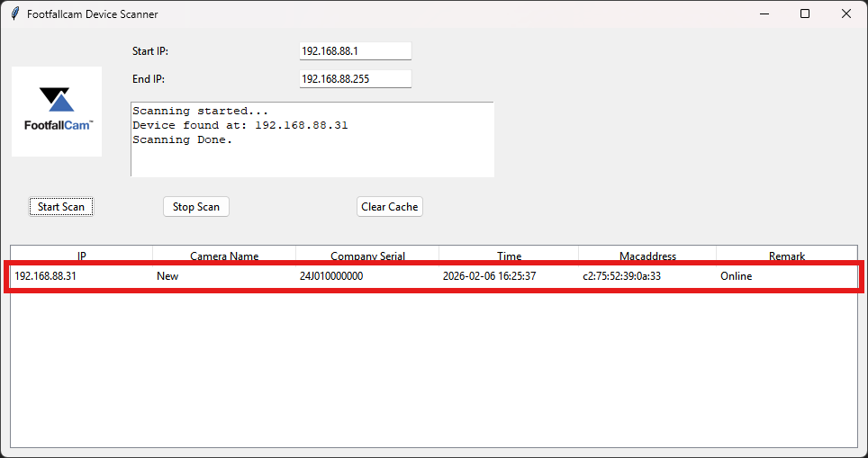
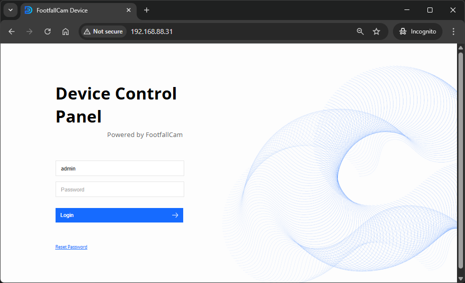
- Visit the IP in the browser to access the Centroid's Device Control Panel
WiFi
If your network does not support DHCP, Centroid will be unable to get an IP. In that case, we can connect to the Centroid's WiFi to configure it.
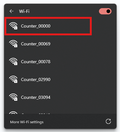
- Turn on the wifi and connect to Counter_XXXXX where the last 5 digits is the last 5 digits of the serial, contact Footfallcam for the password.
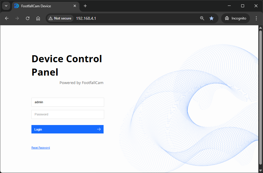
- Visit 192.168.4.1 in the browser to access the Centroid's Device Control Panel
Network Settings
Steps to configure networking settings differ based on the site network environment
*Ideally, Centroid should be in the same LAN as the CCTVs, NVR/DVR devices to be added to Centroid for footfall data collection.
**Note: If the site network IP address range is 192.168.8.1-255, please contact FootfallCam support to assist as it clashes with the Centroid internal IP addresses.
DHCP
-
No manual configuration required, Centroid is in DHCP mode by default, just connect up its ethernet port to the router or switch
-
If internet access is available, Centroid should be blinking blue, green otherwise.
STATIC IP
- If the site's network does not support DHCP, the Centroid will not be able to obtain an IP address. Access the Centroid's device control panel using the WiFi method mentioned above.
- Login and navigate to Config > Network
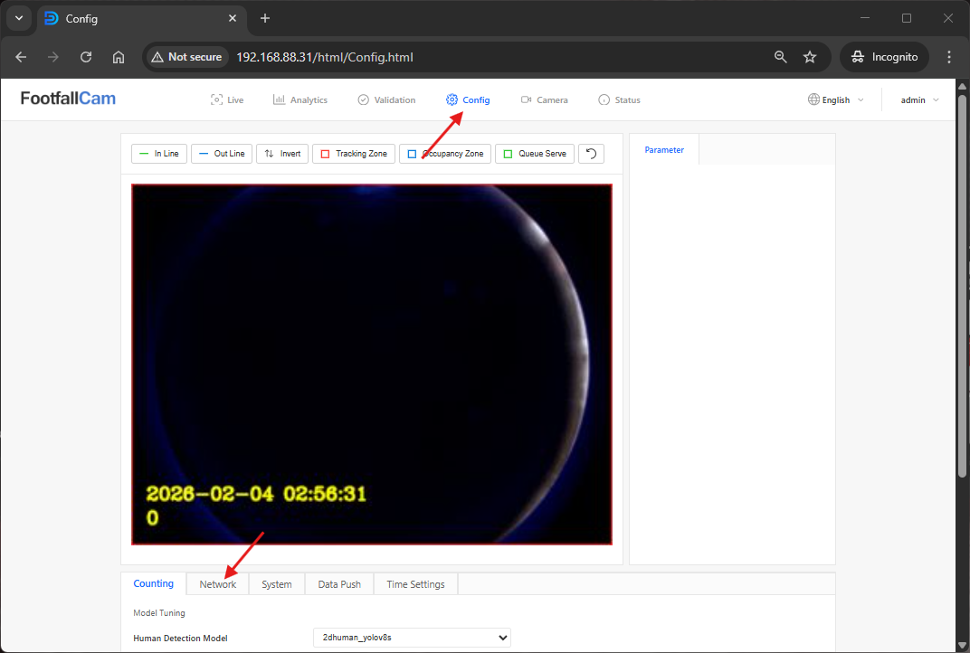
- Select Static IP and enter the IP address, Subnet Mask and Gateway. Click save.
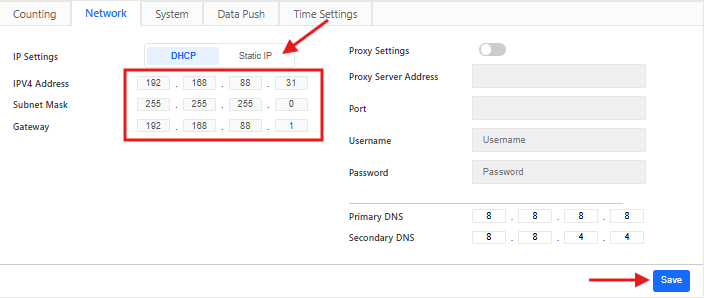
- The device will be rebooted
- After rebooting, if the static IP is valid and the Centroid can obtain internet connection, it should be blinking blue, green otherwise.
Device Allocation
- Provided there is internet access on site (i.e. Centroid is blinking blue light), you may proceed to allocate the device to the FootfallCam server.
- Make sure your laptop ethernet port is connected to the same router or switch as the Centroid.
- If Centroid is in the default DHCP mode, you may use the FFC Pro2 & Centroid Scanning Tool to find out the IP address of Centroid. For static IP, you already know the IP address.
- Visit the IP in the browser to access the Device Control Panel. Login and go into `Config`page, under `System` tab, enter the desired Device Name and the Site Pairing Code (you may get it from V9 portal, see here) accordingly. Then click on the `Save` button to apply the setting and pair the device.
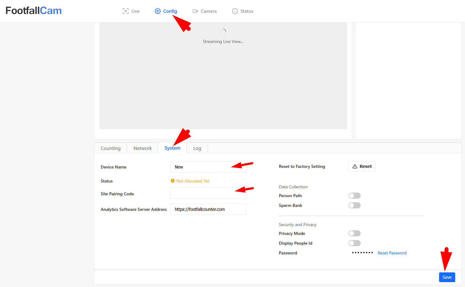
- The Centroid should be in static blue light once it is allocated successfully.
Bind CCTVs to Centroid for Footfall Data Collection
- Go to the `Camera` page, then click on `Add Camera` button to start binding CCTVs. Enter the username, password, camera name, IP address, Vendor and Model (optional) accordingly. See image below for an example:
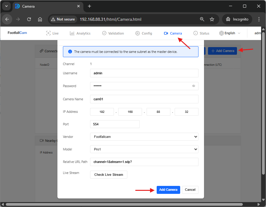
- Vendor and Model is optional, it helps to pre-fill the `Relative URL Path` below according to the format of the selected vendor. If you know the `Relative URL Path` for your device, you may skip this.
- For the `Relative URL Path`, it is referring to the URL portion in the RTSP link after the port number. Using FootfallCam device as an example, the RTSP link is rtsp://<ip_address>:554/channel=1&stream=1.sdp?, so its relative url path would be `channel=1&stream=1.sdp?` as shown in the image. If `Vendor` is selected, this will be pre-filled, you may modify it if the relative url path for your device is different from the pre-filled one.
- You may use the `Check Live Stream` button to confirm the RTSP link connection is okay. Then click on the `Add Camera` button to save the CCTV settings.
- The added CCTV would appear in the `Connected Camera` list as shown below:
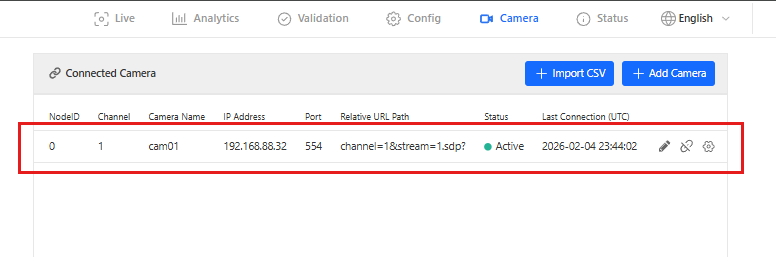
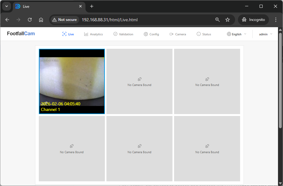
- Go back to the `Live` page, you should see the CCTV video stream you just bind is displayed.
Note:
- For FootfallCam devices to access and process live RTSP video streams from on-site NVR/DVR and CCTV cameras, all devices must reside in the same local subnet.
- If the FootfallCam device and the CCTV system are on different subnets, and subnet separation must remain, please consult your network administrator to add inter-VLAN routing or static routes between the two subnets.
Site Network Requirements for using FootfallCam Centroid
Firewall Whitelisting Requirements
- To ensure uninterrupted communication between FootfallCam Centroid and FootfallCam Cloud services, please ensure the IP addresses and ports listed in Network Outbound Firewall Rules are whitelisted in the site's network firewall, proxy, and VPN security rules.
Centroid CCTV Network Deployment Overview
FootfallCam Centroid retrieve CCTV video streams from a CLOSED CCTV network while simultaneously uploading Footfall data to FootfallCam Cloud through a separate Internet-connected network. The diagram below illustrates the available deployment options and how the Centroid can be integrated into your existing hybrid CCTV environment.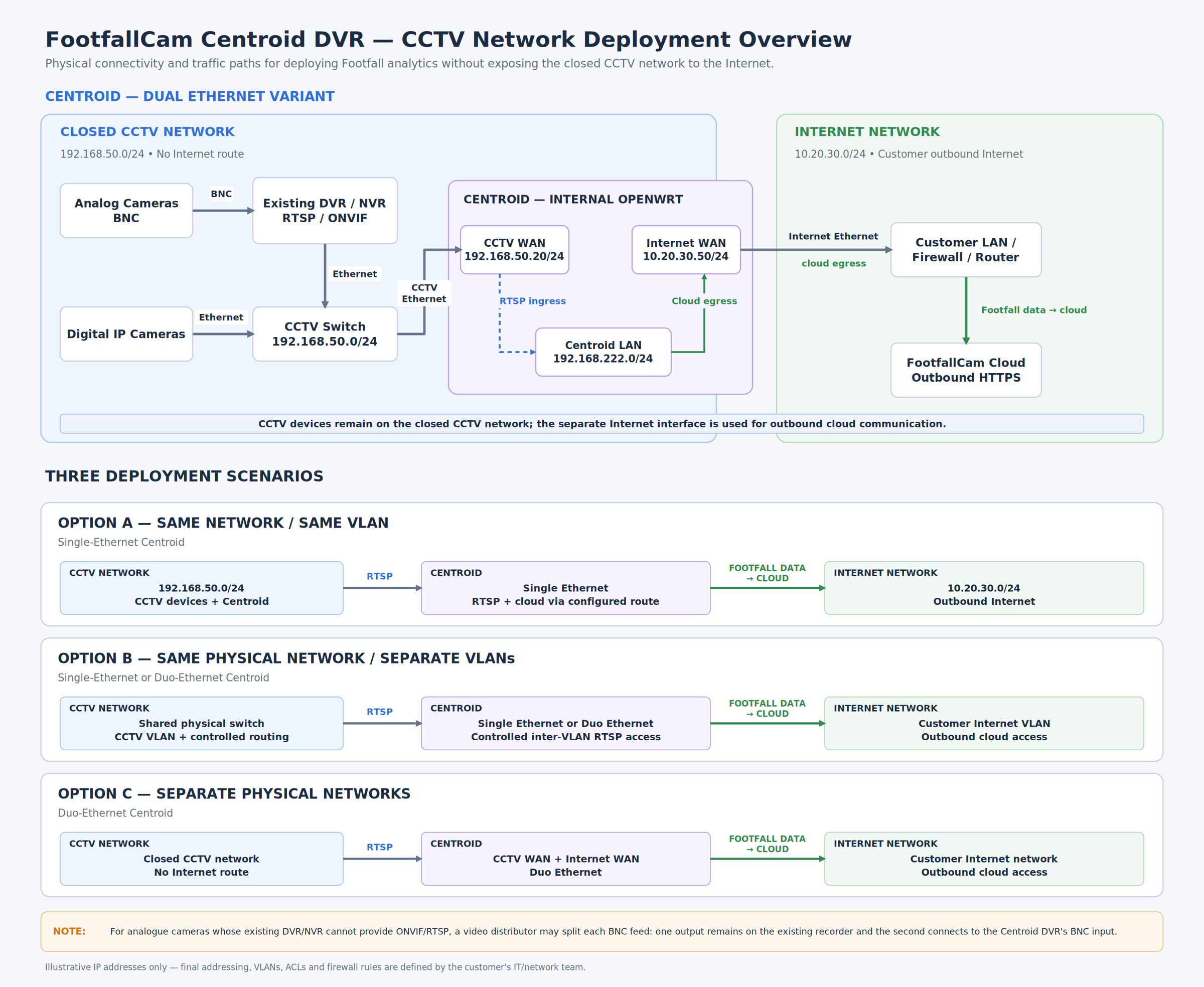
1. Closed CCTV network: FootfallCam Centroid can retrieve video streams via RTSP/ONVIF from compatible existing IP cameras or DVR/NVR systems without requiring the CCTV network to have direct Internet access.
2. Separate Internet connectivity: For the Duo-Ethernet Centroid, one interface connects to the closed CCTV network for video retrieval, while the other connects to your network with outbound Internet access for transmitting footfall data to the FootfallCam cloud.
3. Different network configurations: The diagram covers deployment within the same VLAN, separate VLANs on the same physical network with appropriate inter-VLAN routing, or completely separate physical CCTV and Internet networks.
4. Analogue cameras: Where the existing DVR/NVR cannot provide RTSP/ONVIF streams, a video distributor can be used to split the analogue video feed, allowing the existing recorder to continue operating while providing a separate feed to the Centroid DVR.
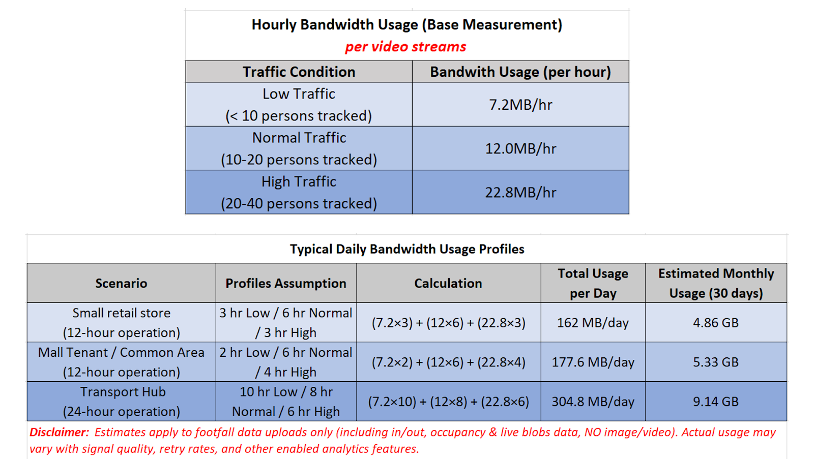
Bandwidth Usage Estimation
Entrance Counting ONLY
-
2MB/day (12hr operation), assume hourly 100 people In&Out footfall activities.
Path Map Playback Enabled
-
On average 60MB/day (12hr operation), assume 20 people being tracked actively in the liveview.
-
Can opt for out of operating hour data uploading
Live-blobs Viewing Enabled: