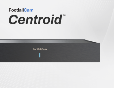















2.1 FootfallCam Centroid Installation
2.1.1 Installation Requirements
 |
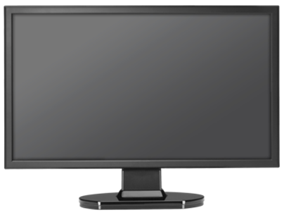 |
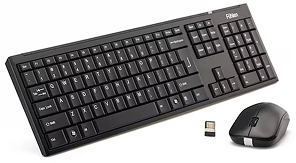
| Keyboard and mouse | Monitor with HDMI connection |
 |
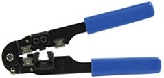 |
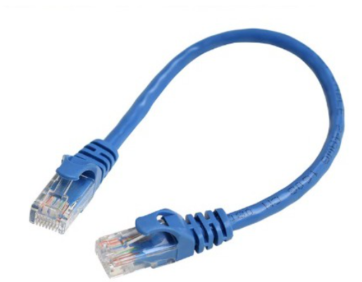
| Cat5e network cable to connect the Centroid from the router. | RJ45 crimp tool to terminate the cat5e network cable. |
|
 |
| Laptop for IP address searching within the same network | General height of installation for counter ranges from 3 metres and above. |
2.1.2 Hardware Connection
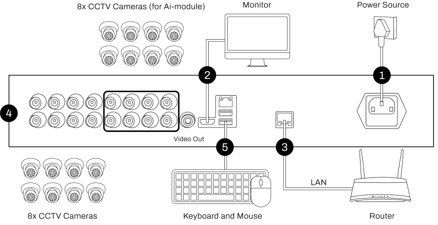
| 1. Power | Connect the power cable to the Centroid and a power outlet. |
| 2. Display | Connect the HDMI cable from the Centroid to your monitor/TV. |
| 3. Network | Connect an Ethernet cable from your router to the Centroid. |
| 4. Cameras | Connect Analog Camera cables to the BNC connector. (Channel 1-8 for AI-module) |
| 5. Keyboard and Mouse | Plug the USB keyboard and mouse into a USB port on the Centroid. |
2.1.3 Centroid Initial Setup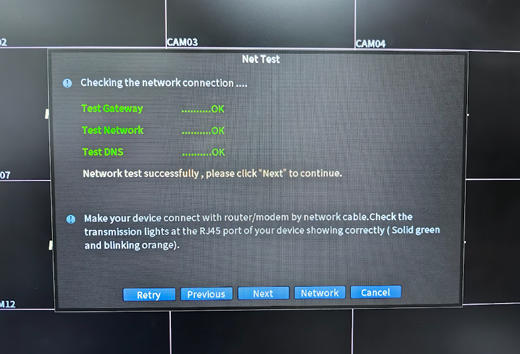
|
STEP 1 - Set Timezone and Language: Select the required timezone and language. STEP 2 - Create Account: Create a username and password. Set a security question or pattern lock. STEP 3 - Run Network Test: The system will automatically run a Network Test. Make sure all indicators show OK. STEP 4 - Set Static IP Address: Click [Network] and set a static IP address to prevent the IP address from changing. STEP 5 - VMS App (Optional): Scan the QR code on the screen to download the VMS app for remote monitoring. |
2.1.4 Select Centroid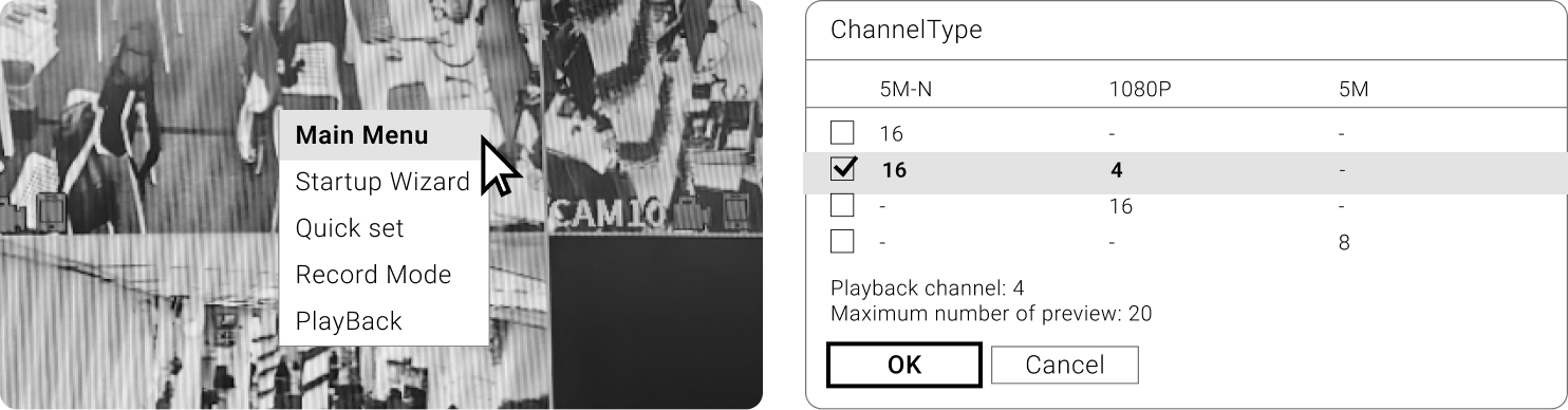
|
STEP 1 - Right-click on the interface and go to Main Menu > System > Digital > Channel Type. STEP 2 - Under Channel Type, select the second row for the 5M-N (Analog Cameras - Local) and 1080P (IP Cameras) channels. STEP 3 - Click [OK] to confirm the selected channel. |
2.1.5 Optional: Add IP Camera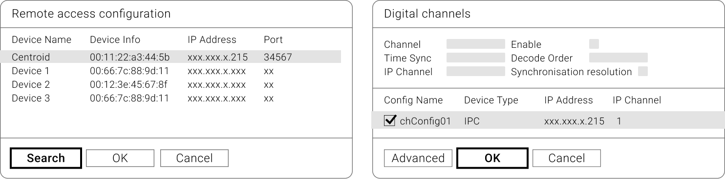
|
STEP 1 - Right-click on the interface and go to Main Menu > System > Digital > Channel Type. STEP 2 - Under Channel Type, select the second row for the 5M-N (Analog Cameras - Local) and 1080P (IP Cameras) channels. STEP 3 - Click [OK] to confirm the selected channel. |
2.2 FootfallCam Centroid Indoor Installation
2.2.1 Installation Tools
|
|
|
| Cat5e network cable to connect the Centroid from the router. | RJ45 crimp tool to terminate the cat5e network cable. |
 |
|
| Scissor to reduce the length of the cat5e network cable. | General height of installation for counter ranges from 3 metres and above. |
2.2.2 Cabling Guidelines
2.2.2.1 Wiring Setup Installation
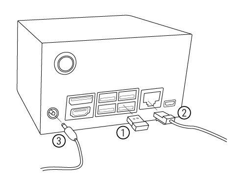
|
STEP 1 - Insert the attached Wi-Fi dongle into any one of the USB 3.0 ports. STEP 2 - Run a Cat5e network cable from the router to the Centroid. STEP 3 - Connect the attached power supply adapter to the power jack. The Centroid will power on and boot up automatically. |
2.2.3 Cable Crimping standard
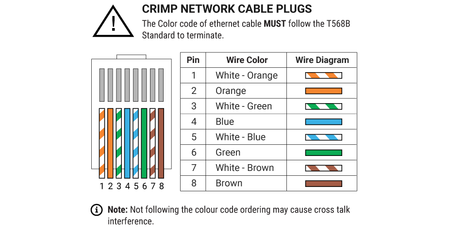
Installer MUST follow TIA / EIA 568B colour code for crimping the Cat5e cable to avoid crosstalk interference.